Bluetooth LE (low energy)
Introduction to my Project
My Bluetooth project is to replace a simple wireless door bell I use to monitor a gate I can't see from my house.
The simple wireless door bell does not work when the battery goes flat. No surprises there, except when an unexpected visitor arrives!
I therefore needed a wireless gate monitor with some ability to raise an alarm for abnormal conditions such as a battery going flat.
Bluetooth History
Bluetooth technology started out in the mid 1990s as a wireless replacement for 2 wire serial data communication.
One wire for transmit and the other for receive.
Bluetooth is found in many modern applications and devices.
Some common uses are: linking a mouse to a computer, linking a mobile phone to a computer, linking a camera to a mobile phone, speakers, headphones, earphones, etc
Bluetooth Origins
With some help from
http://www.pcworld.com/article/2061288/so-thats-why-its-called-bluetooth-and-other-surprising-tech-name-origins.html
Bluetooth was borrowed from the 10th-century, second king of Denmark, King Harald Bluetooth; who was famous for uniting Scandinavia just as we intended to unite the PC and cellular industries with a short-range wireless link.
My Bluetooth LE Project
After first looking and XBee and Wifi technology, I discovered Laird BL652 Bluetooth LE modules for simple low power data links.
This module is part of the emerging IoT (Internet of Things) where devices, appliances and wearable technology needs short range low power communication.
- The BL652 is an all-in-one programmable device.
- Consumes very little power in standby.
- Has a range of up to 100m.
- Once paired with another Bluetooth device is able to connect up again very quickly, even from standby.
- BL652 modules are fairly low cost - about NZ$12.50 each as at December 2016.
- I had previously looked at an Xbee module with an attached Pic microcontroller option. I stopped work on it because there were two programmable devices, two different architectures and programming languages were required a well as a larger more complicated PCB.
- I had also looked at the ESP8266 WiFi module. The module is programmable but took lots of power, is too complicated for simple applications and took a long time to link up from standby.
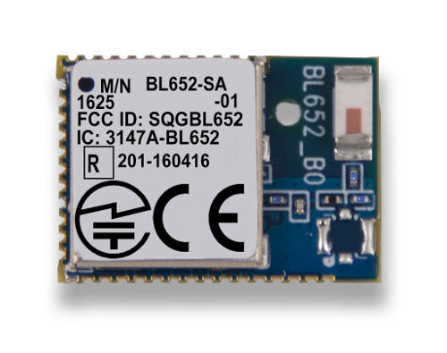
A BL652 Bluetooth LE (low energy) module from Laird. Measures 14 x 10mm. Capable of data communication up to 100m range. Is programmable and draws about 8mA on transmit and 1.2uA on standby. Great for battery powered projects....
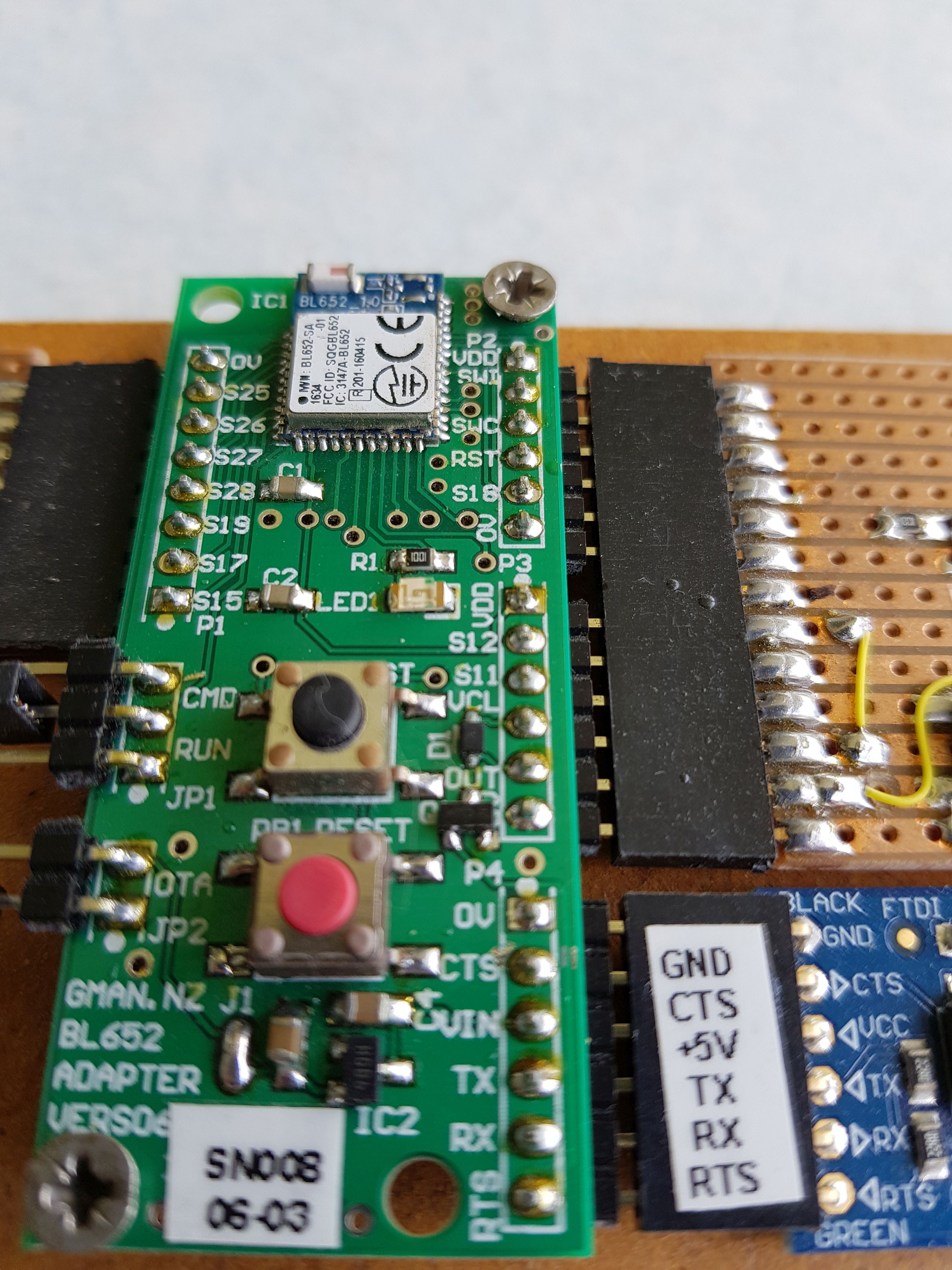
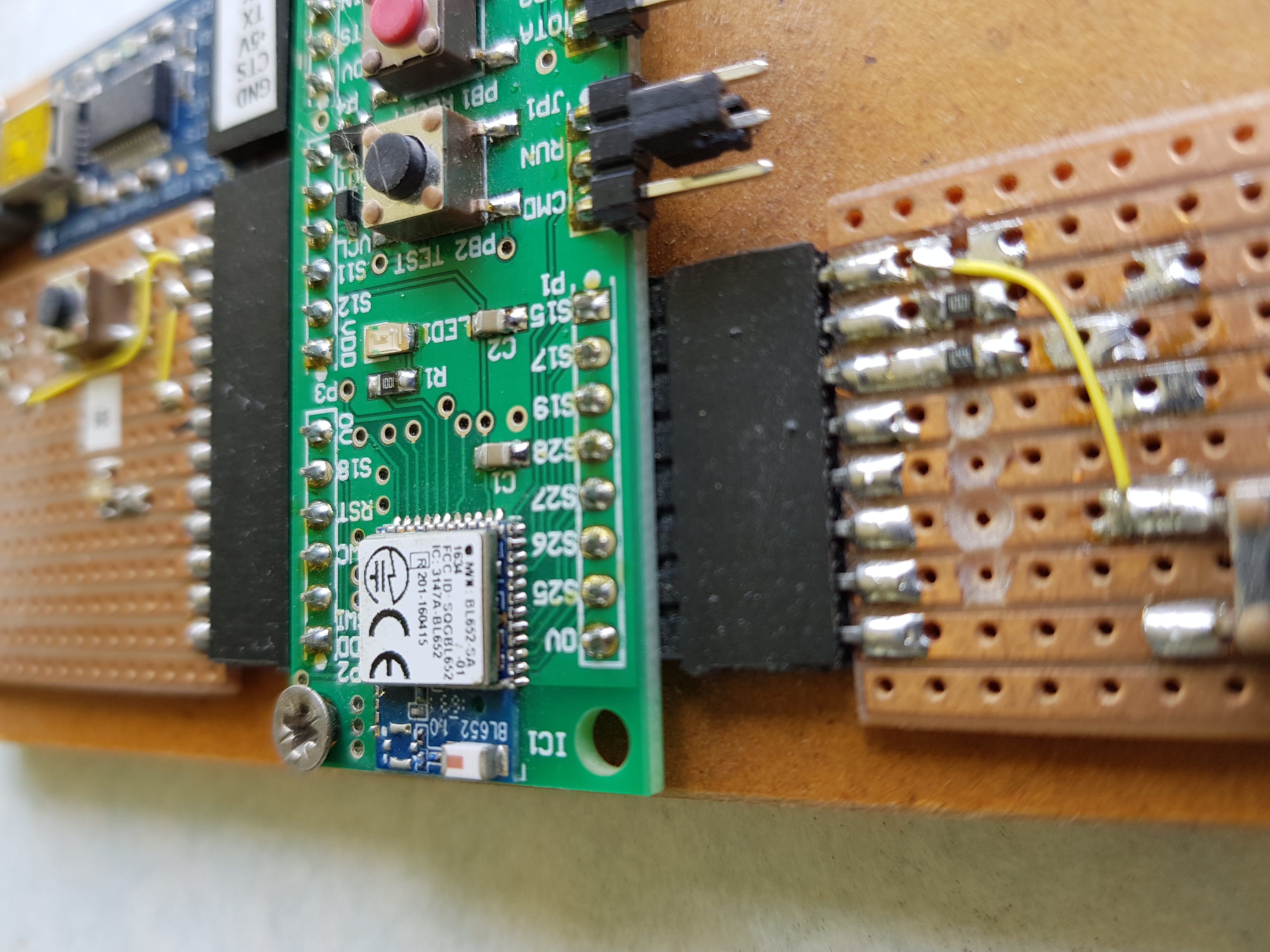
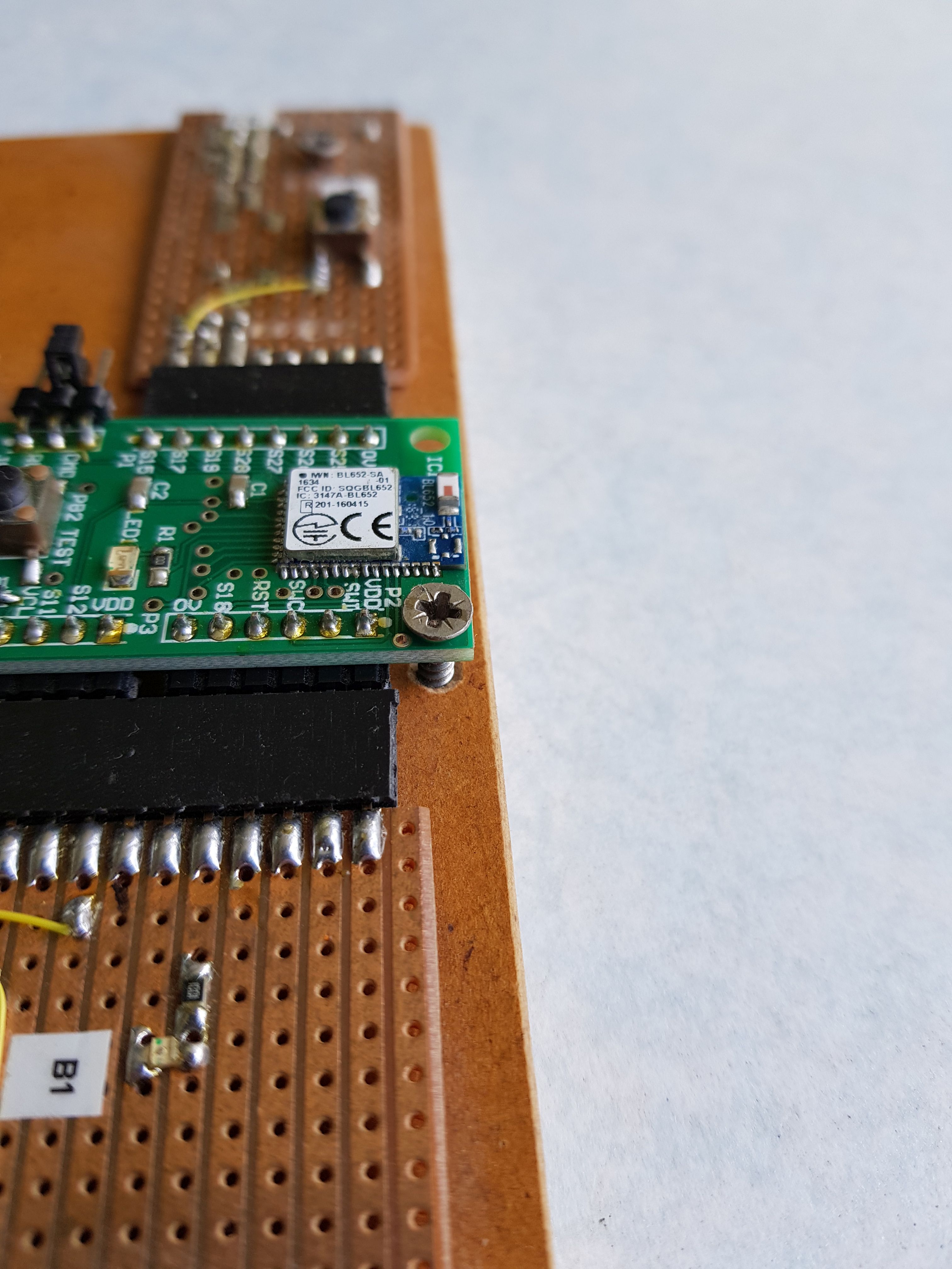
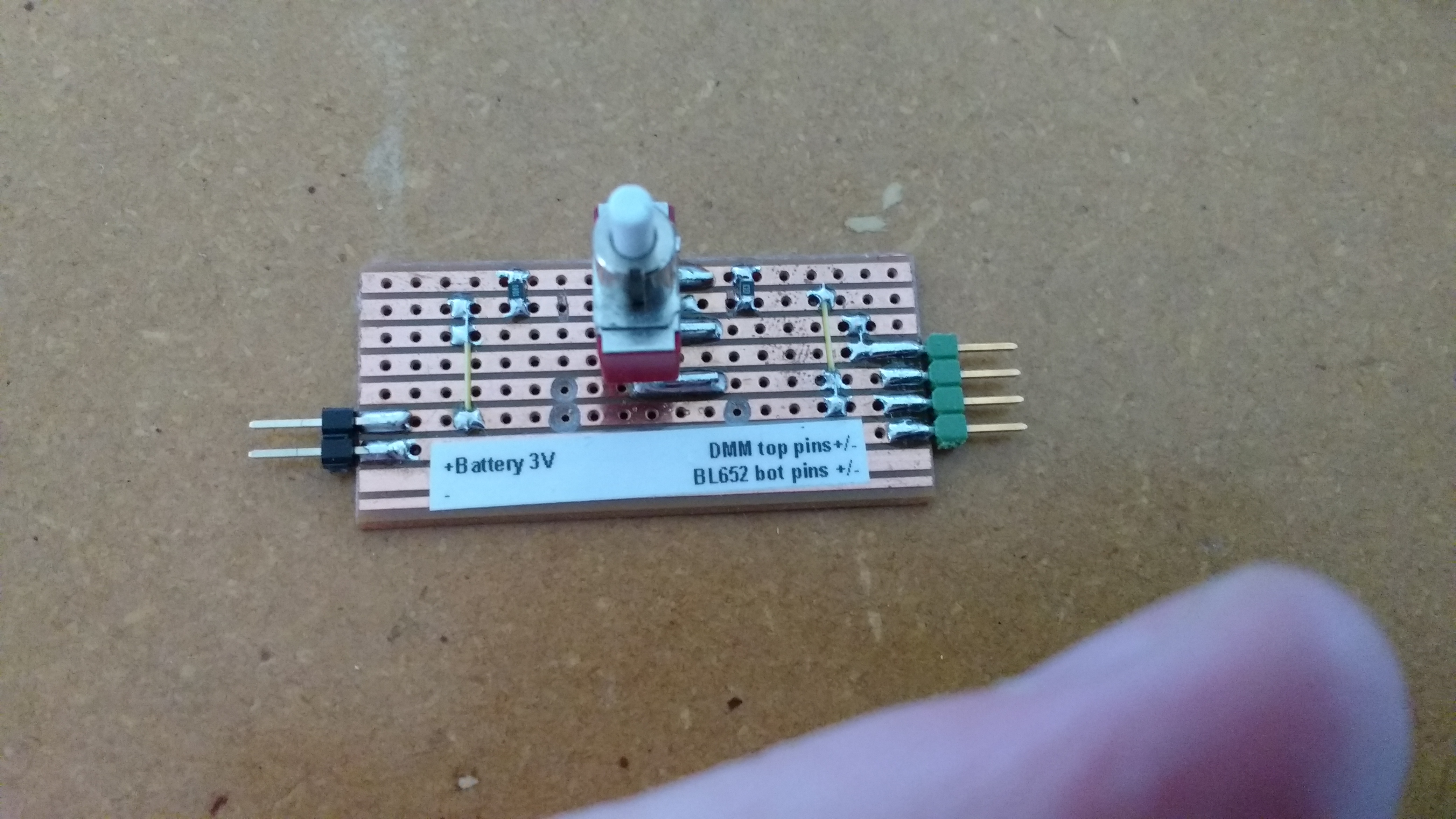
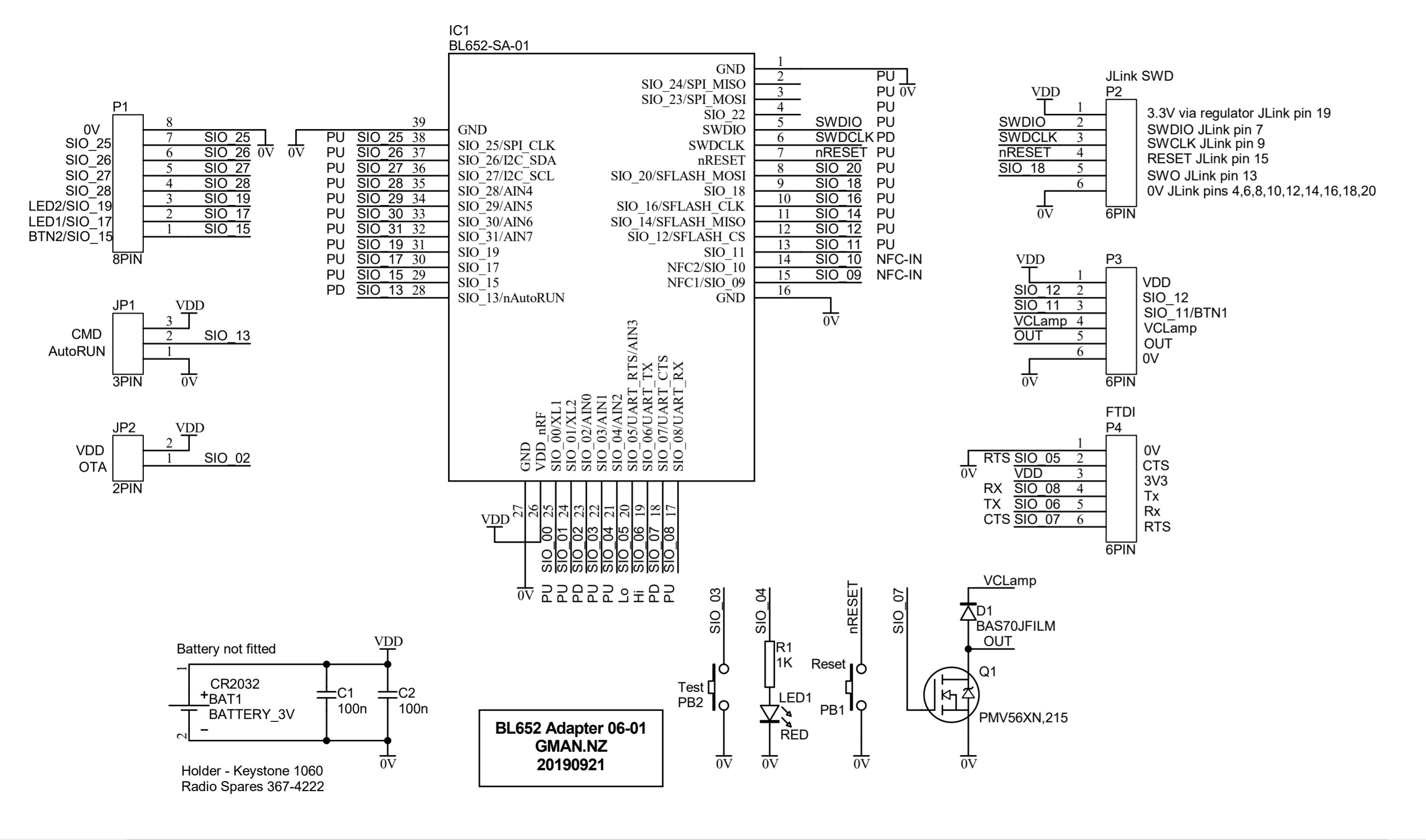
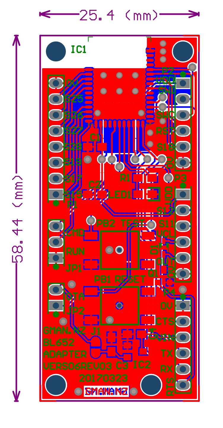
Here is my BL652 adapter.
|
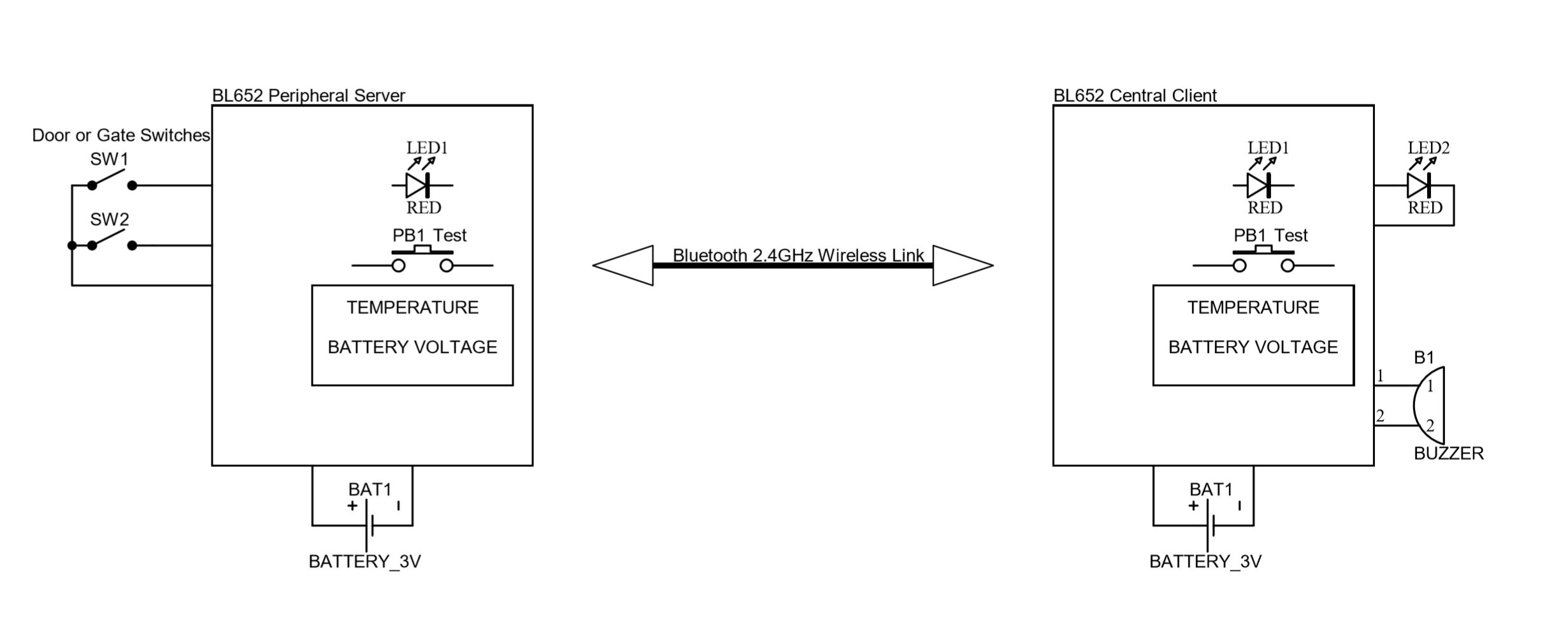
Here is an example of my intended application Basic Application - Door and gate monitor.
My BL652 BLOG...
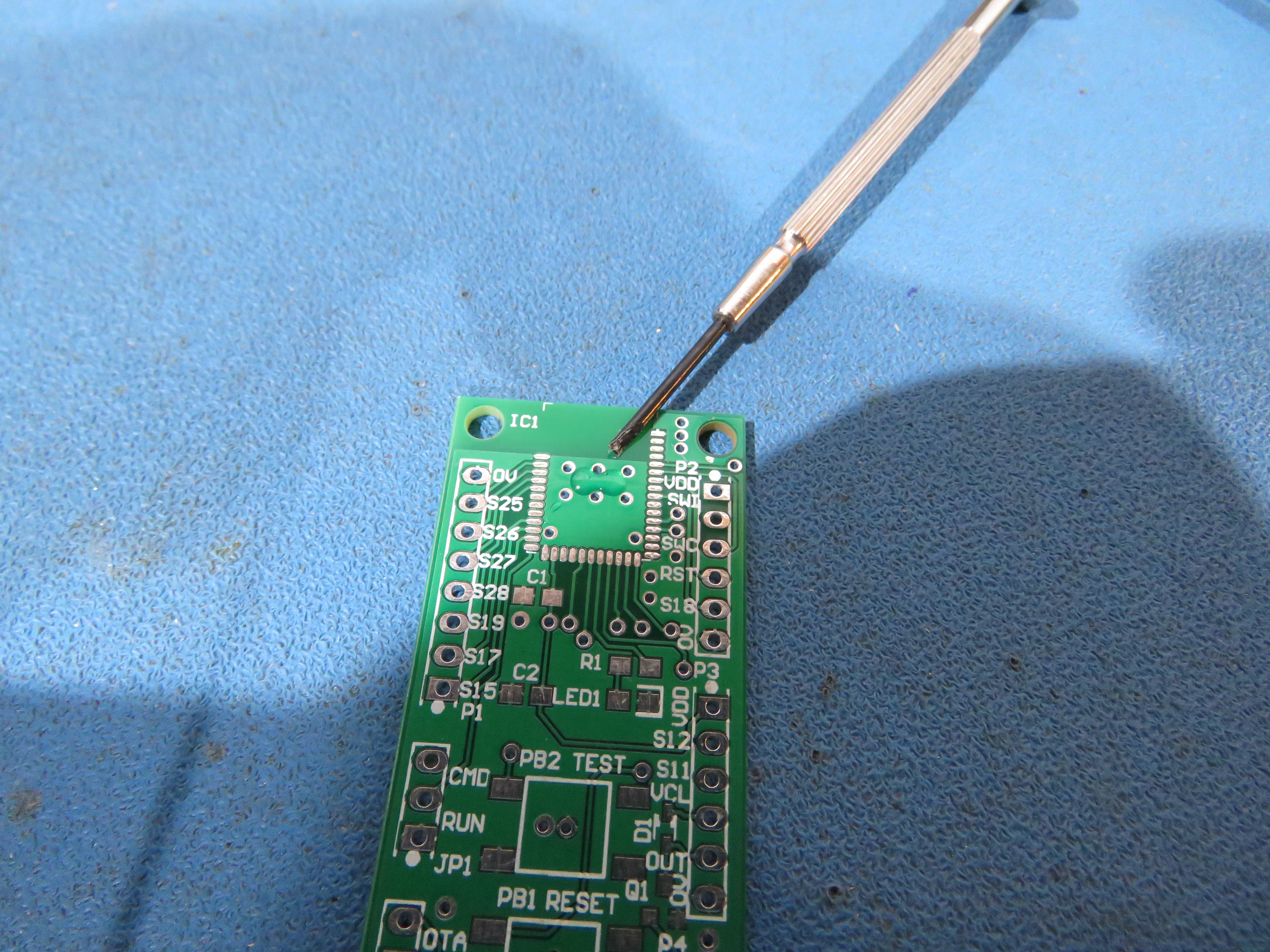
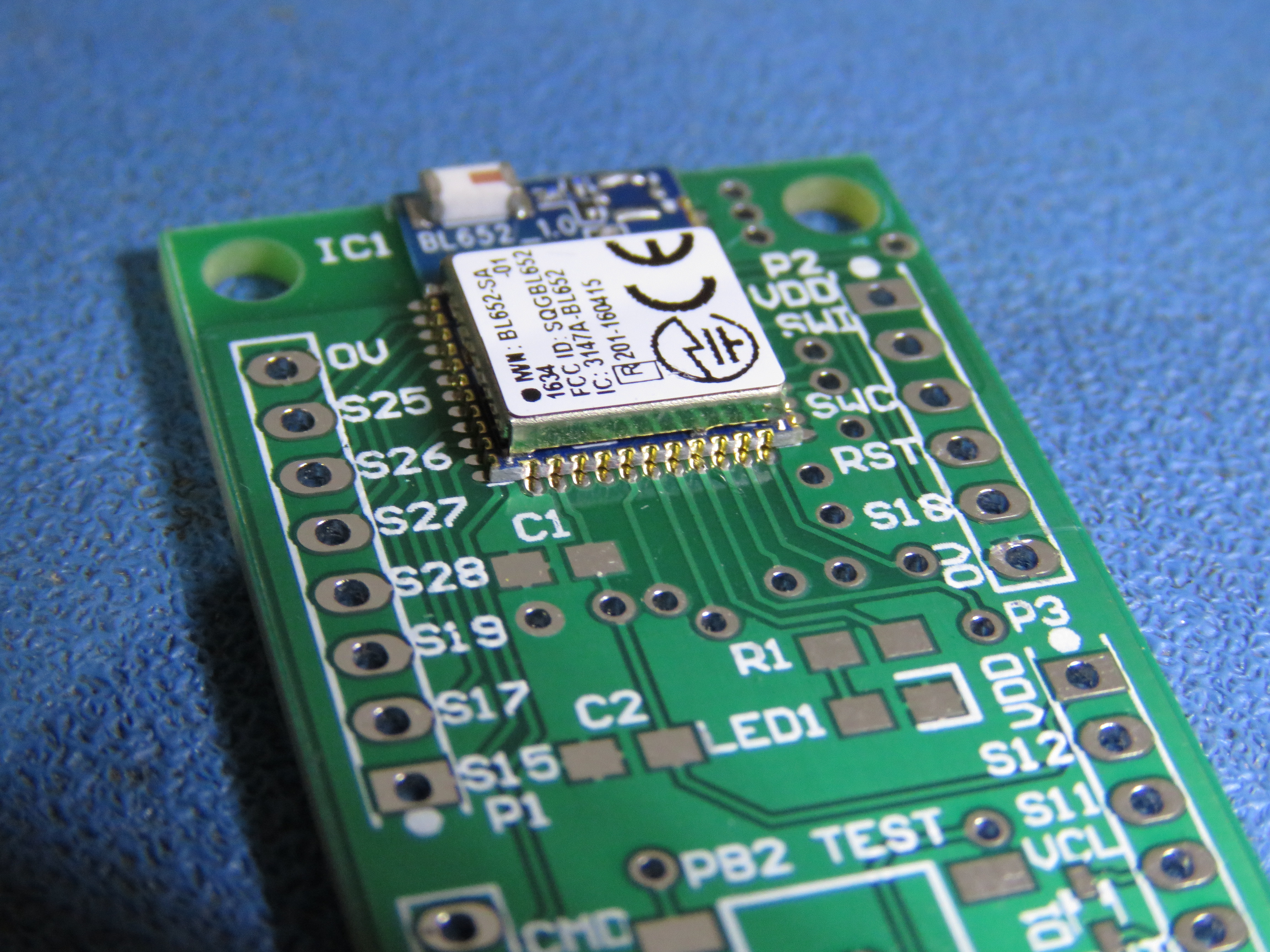
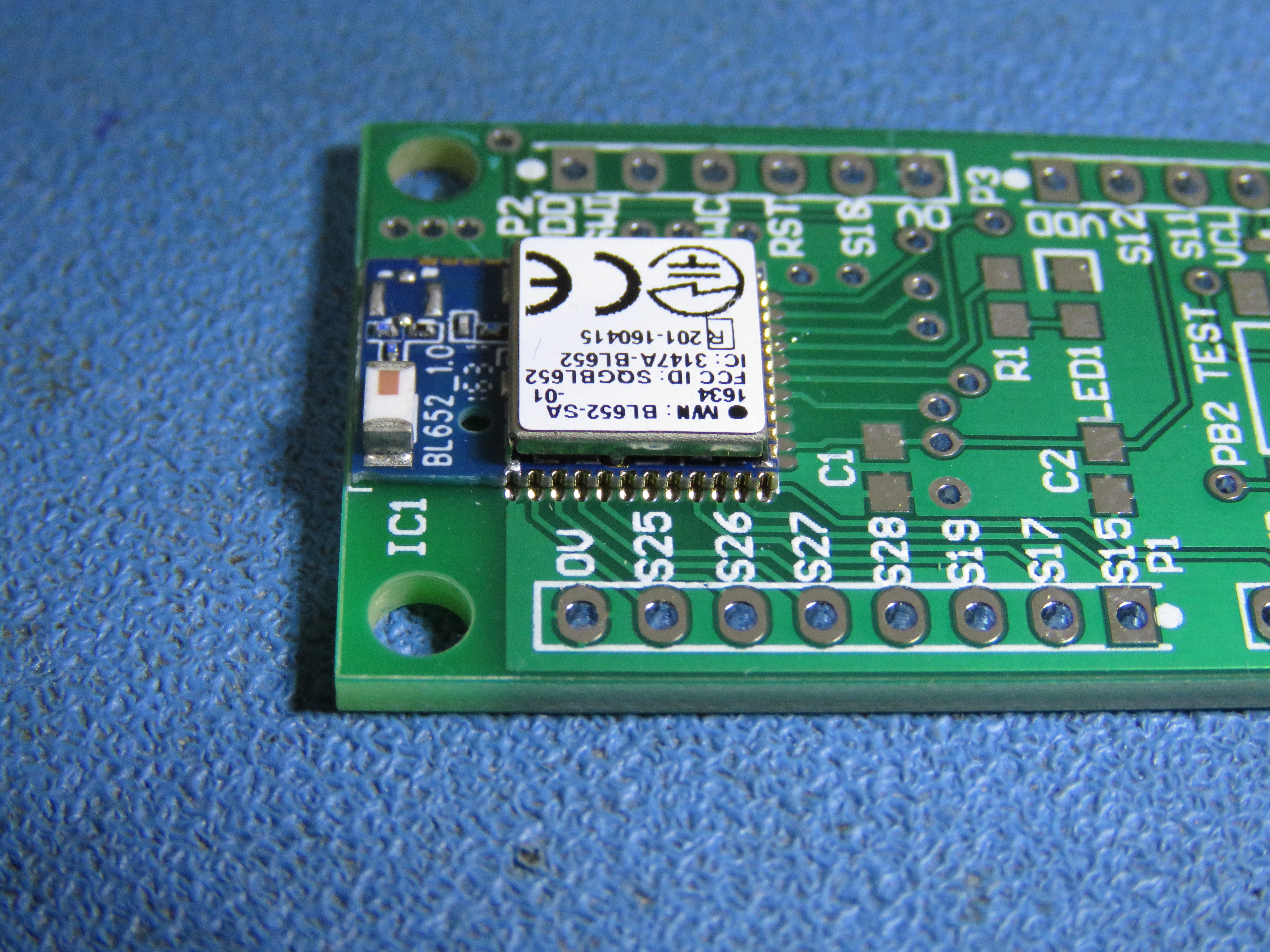
15 December 2018 Some catch up notes on soldering the BL652 to a PCB. BL652 pin pitch 0.75mm Weller soldering iron tip used approx 1.5mm diameter Solder 0.7mm Lead/Tin Iron temperature 320C. For the first few BL652 attachment to the PCB, I tacked one pin with solder and checked the remaining pins for alignment with the PCB. Often this required many attempts with re-tacking. I felt the process put a lot of stress on one pin and on the PCB pad. My current method is to glue a BL652 to a PCB with a 5 minute epoxy adhesive. Excess glue can run out through the via holes if required. This gave plenty of time for alignment. I left the glued BL652 for several hours before soldering. Here a some views of the results:
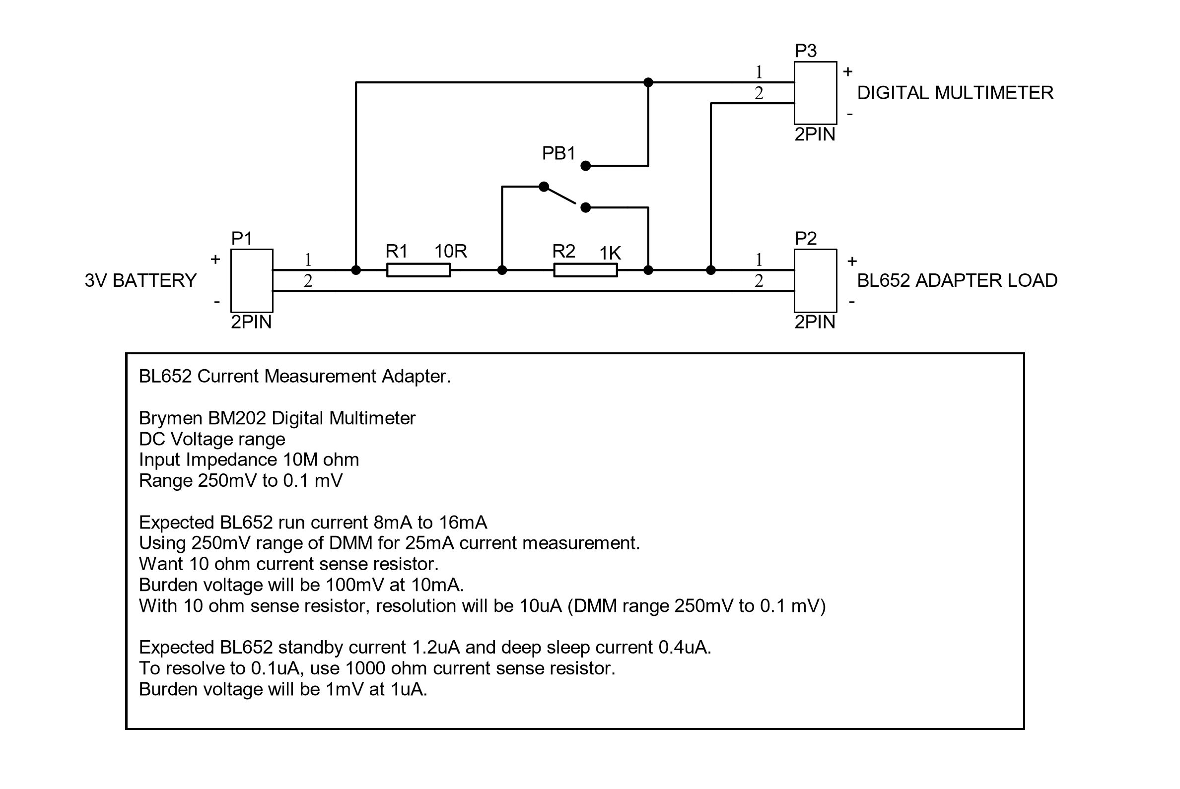
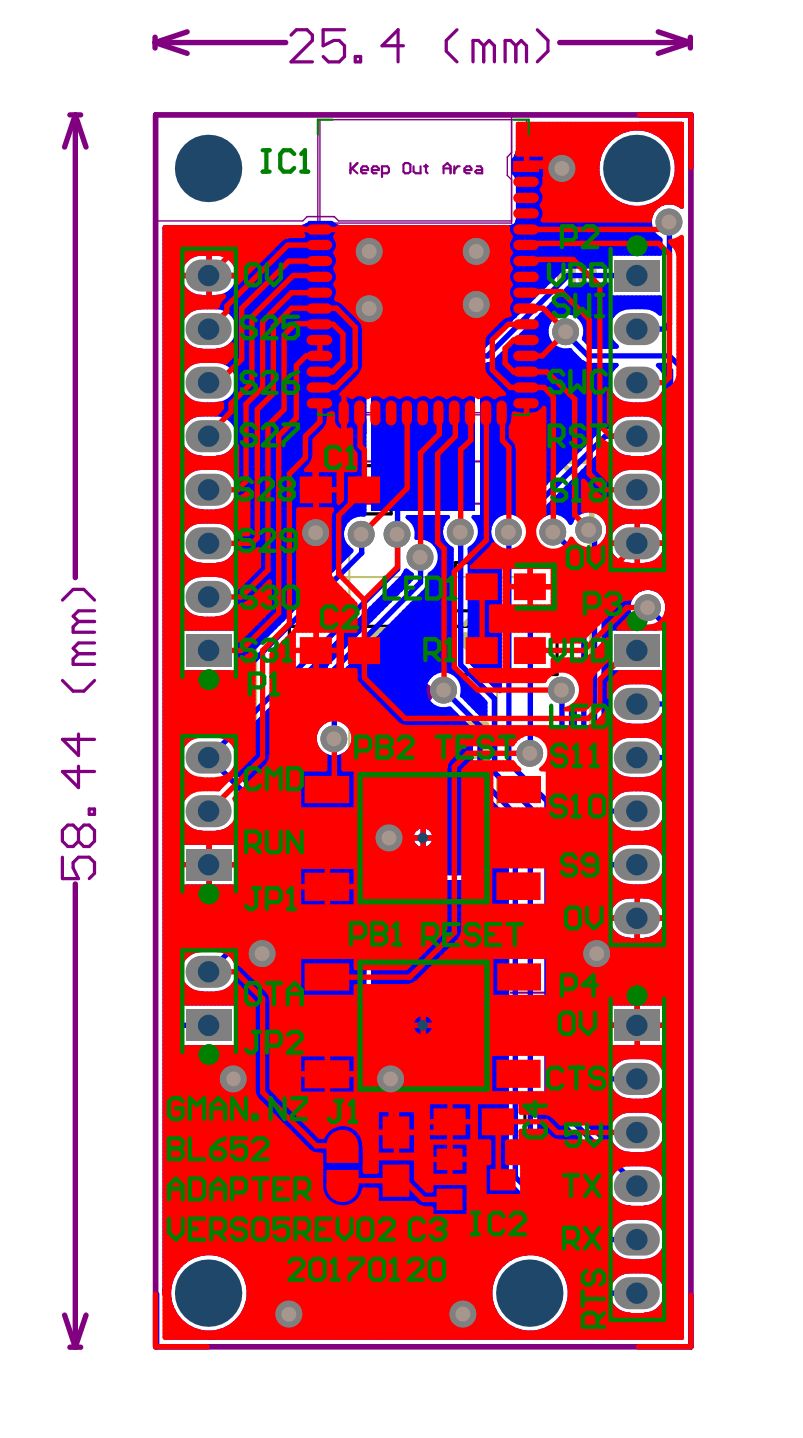
14 December 2018 Added schematic 06, PCB CAM file 06-03 and a basic BOM at the bottom of this page.
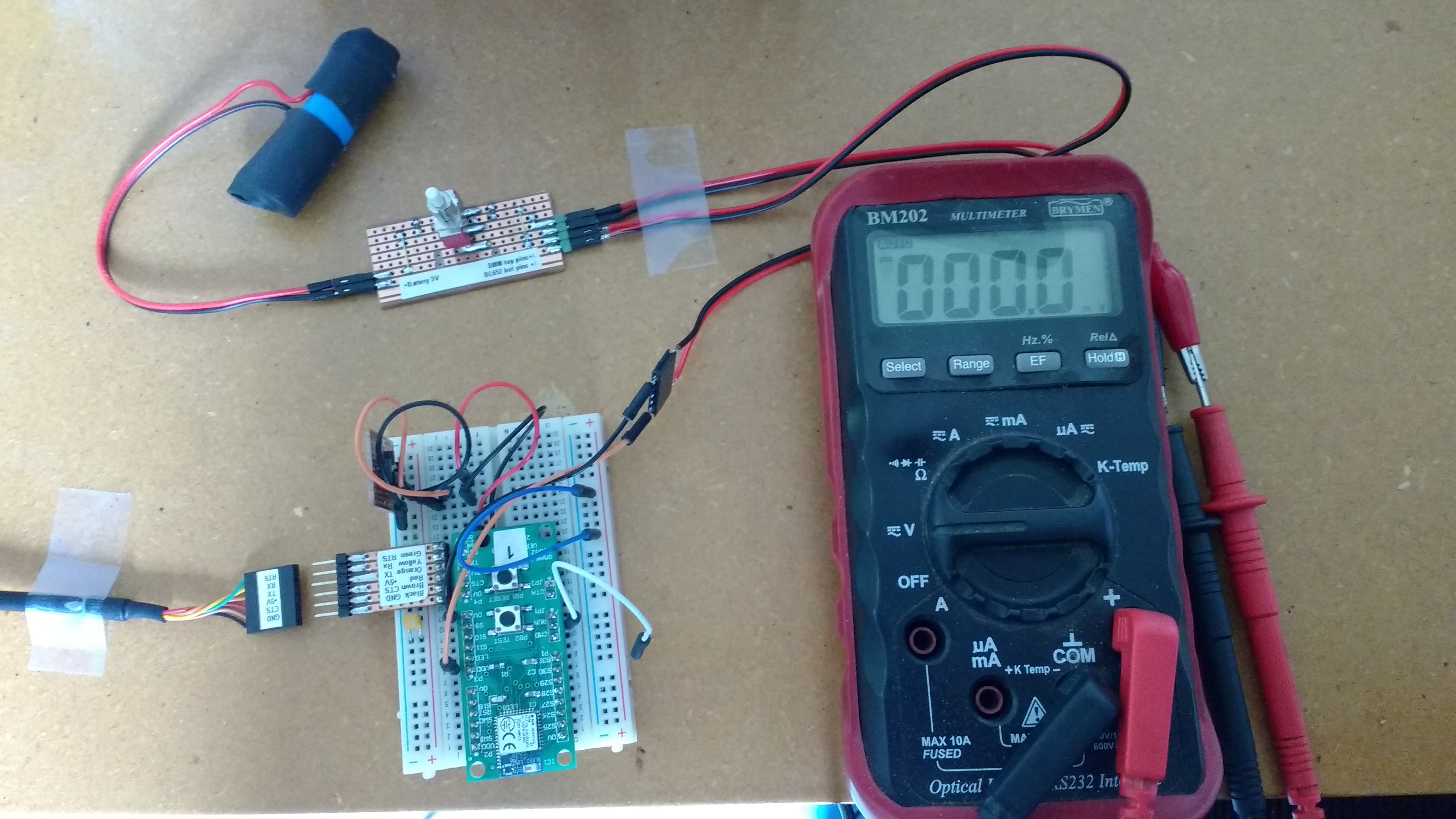
24 April 2017 Some BL652 current measurements. Supply voltage Vdd 3.33 volts using a LiFePo4 cell. Serial port disconnected from module during measurements. Room temperature about 16C. Module reset 5.4mA Peak current briefly after reset released 17mA Autorun Beacon 100ms interval 1.4mA average. Autorun Beacon 10000ms (10sec) - between Beacon broadcasts 1.8uA Using Laird application and standby mode LP.Low.Power.Deep.Sleep.sb 1.8uA
3 April 2017 Today I have decided I will use Bluetooth LE broadcast beacon in my application. The Eddystone TLM (telemetry) format seems to suit my application. In order to keep the Eddystone data frame format pretty standard I plan to use: - Peripheral module MAC address for broadcast ID. - Module battery voltage - Module temperature. - Leave the PDU advertising count in place - Leave the Beacon time since boot in place. - Append a byte for GPIO to monitor switch inputs.
Two Laird applications I found very useful to get started were: adv.minimum.app.to.advertise.sb using one module as a beacon. BleScanGetAdvReport.sb using another module as a central scanner. To examine iBeacon and Eddystone beacon formats I used the Laird application example: $autorun$.beacon.sb
27 March 2017 Here is my latest breadboard with BL652 breakout PCB 05-02. Using v28_0_1_ALPHA_v5_1 firmware. Have been running dvks.devkit.sample.app.sb which has a slight modification from the Laird $autorun$.devkit.sample.app.sb. - My Dev Kit program modification reads the BL652 module temperature rather than reading the discrete temperature sensor IC mounted on the development kit board. Used Laird Modulink on my Android phone to test buttons and Leds and can see module Temperature and Battery voltage. Did a range test from my computer desk down to the rear of my back yard... about 30 metres... pretty good considering all the losses in the signal path.
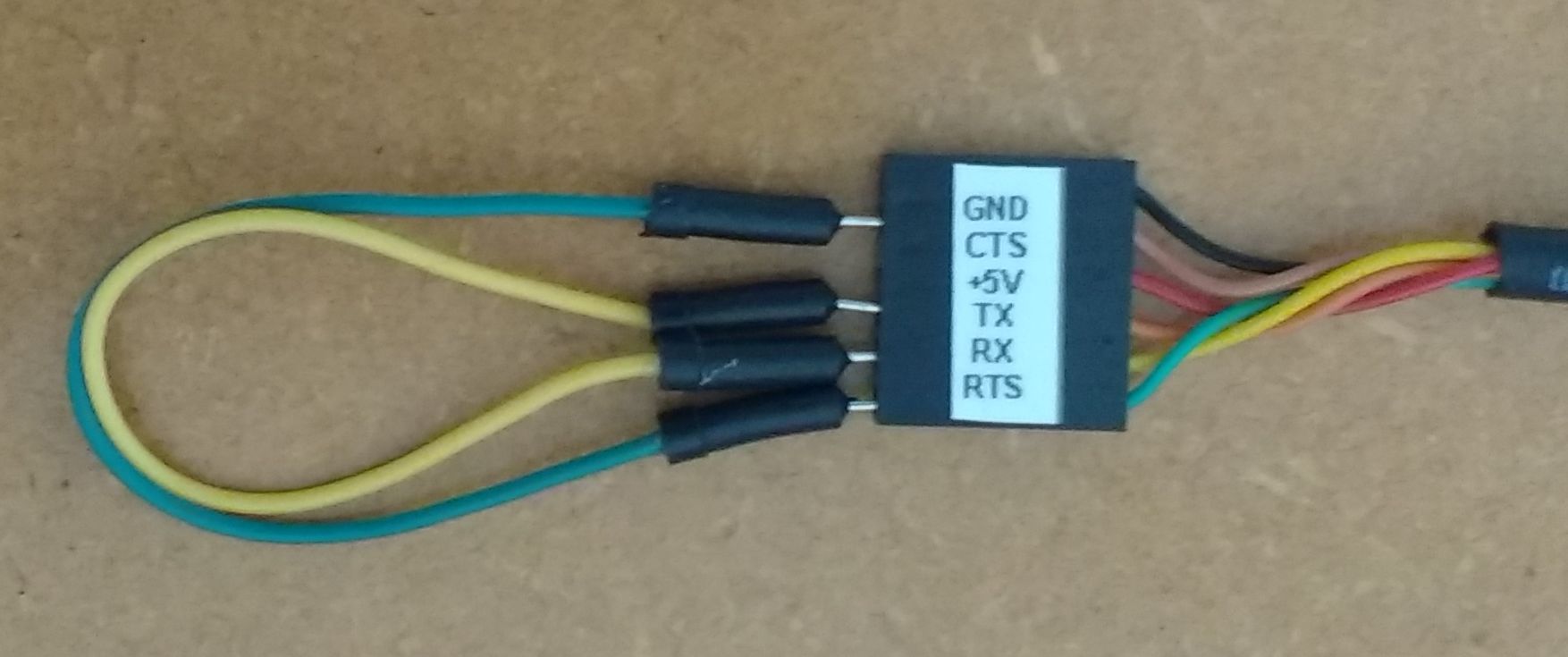
26 March 2017 While learning about the BL652 serial port, I did some testing using the Laird UwTerminalX Speed Test program. Serial loop back testing of the FTDI USB serial adapter.
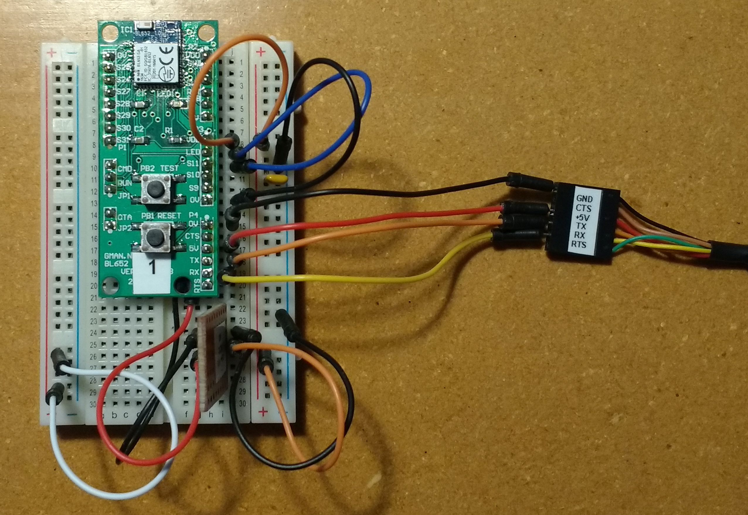
Serial loop back testing of my BL652 adapter using Rx/Tx and no handshaking.
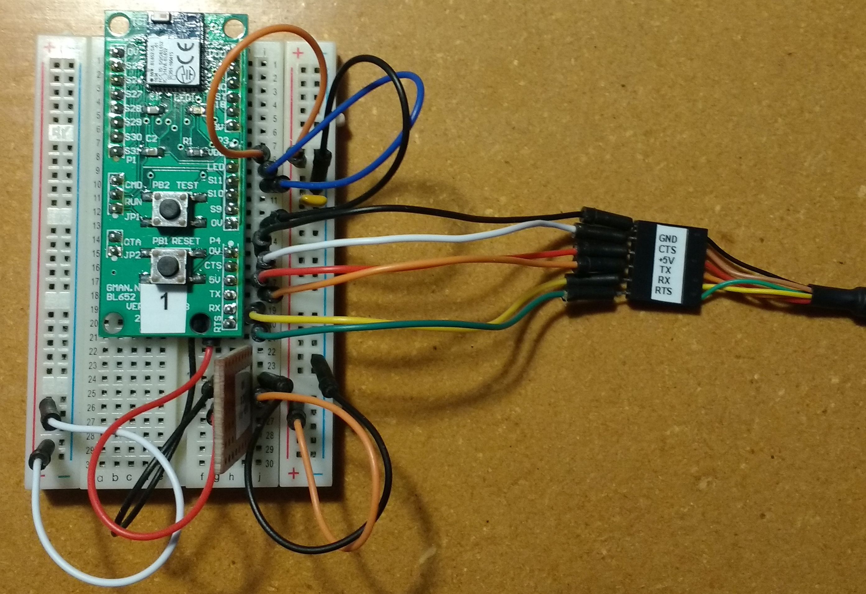
Serial loop back testing using my BL652 adapter Rx/Tx and RTS/CTS handshaking.
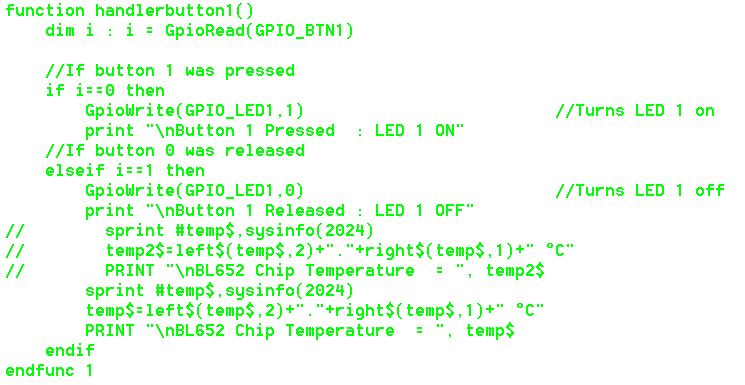
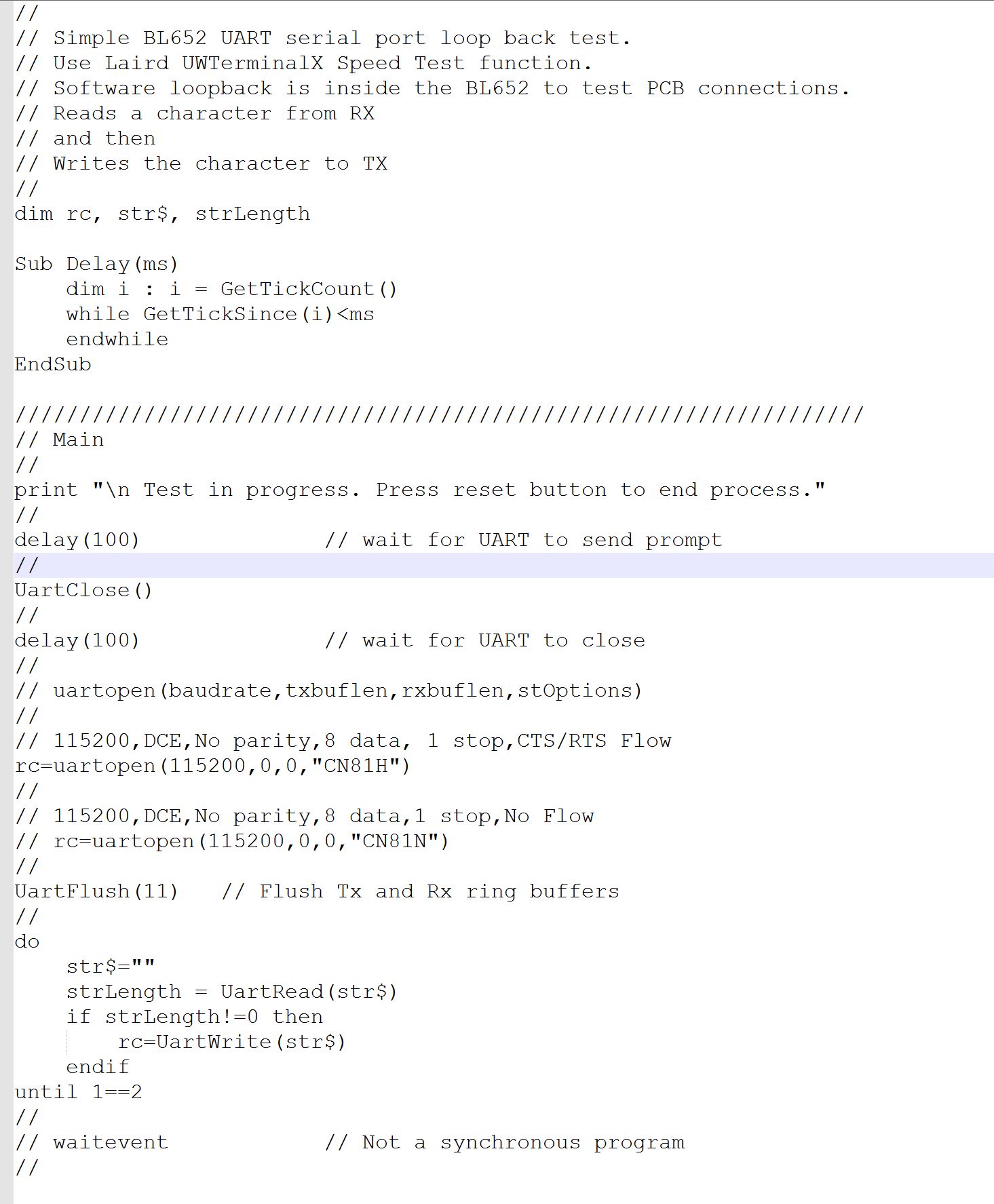
SmartBasic serial loop back test program.
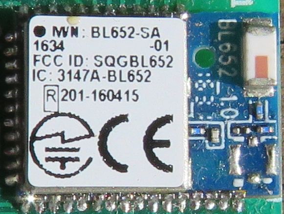
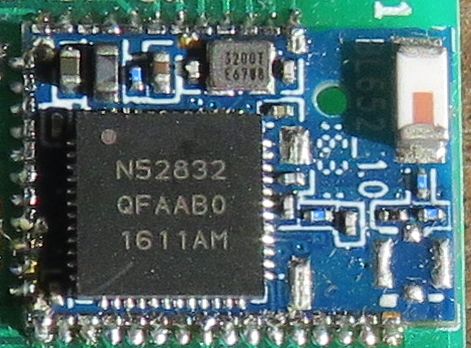
21 March 2017 While I was having trouble with one of my BL652 adapter boards, I decided to pop off the BL652 shield to see what hardware was used. I used a dental probe under one corner of the shield and applied a bit of heat with a soldering iron on an adjacent shield solder pad. To my surprise the shield just popped off. From the components seen, the schematic appears similar to QFAA schematic be found in the Nordic Semiconductor document nRF52832_PS_v1.2.pdf. Shield on:
Shield off:
20 March 2017 Today I discovered that I did not have the serial port handshaking lines RTS and CTS wired up correctly on my BL652 adapter boards. Discovering the problem was masked by successful UwTeminalX operation of AT command access, program loading and running even though I had incorrect RTS and CTS wiring. So for successful UART firmware upgrades the connection requirements must be: Computer Tx connected to BL652 Rx Computer Rx connected to BL652 Tx Computer CTX connected to BL652 RTS Computer RTS connected to BL652 CTS. The computer UART is made using a USB FTDI serial adapter. I was able to upgrade the firmware by UART in all 6 of the BL652 adapter PCBs I have built so far.
28 February 2017 After 4 days with my most recent batch of boards I attempted to repeat a UART firmware upgrade. I am able to get successful sync, see the flash being erased and about 36 seconds into flash write before failure. Same on all 3 boards and on my older boards. Restored the firmware with the Segger Jlink.
24 February 2017 Just received my PCBs from Elecrow. These are my revision 05-02. Assembled 3 boards and tested a couple of Laird applications by compiling, uploading and running... so I was very happy. However, I tried to upgrade all 3 PCBs with firmware by UART from 28.6.1.2 to 28.6.1.4 which failed with a the error message 'Failed to synchronise with the device, retrying'... Gave up, as I don't know what this error message means. I did consider trying to do a UART loopback test. Upgraded the firmware using my Segger JLink. So the earlier firmware upgrade failure where I suspected a faulty breadboard was probably a false positive.
29 January 2017 My new PCBs are in limbo while China celebrates the new year. So while waiting, I have re-arranged my Bluetooth LE web site so that my most recent BLOG is near the top. I have also put some images under the relevant date.
9 January 2017 When I receive my revised BL652 03-02 adapter PCBs I will connect my FTDI UART serial cable directly. No breadboard required. Same applies to connecting the Jlink adapter directly to my BL652 adapter.
7 January 2017 I have now built 3 BL652 adapter boards. Two problems emerged: 1. I had a problem with the JLink not upgrading firmware one of my BL652 adapter boards. It turned out that because plugging the adapter into a breadboard required considerable force I had bent a pin. Fixed the pin and JLink upgrading worked again. 2. UART firmware upgrading sync failure problem I had on 27 December was traced to a problem with a faulty breadboard. By swapping my BL652 adapter boards between the breadboards I was able to pin point the problem. I am now going to look for better quality breadboards :-) As part of my PCB assembly process and verification, I wrote a small SmartBasic program to step through all user available pins and toggle one output bit and look for changes on remaining inputs.
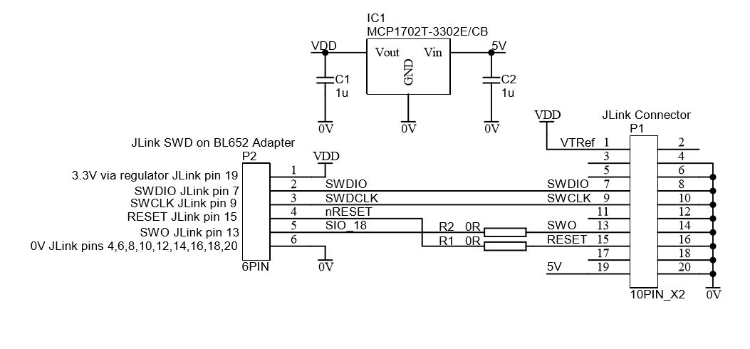
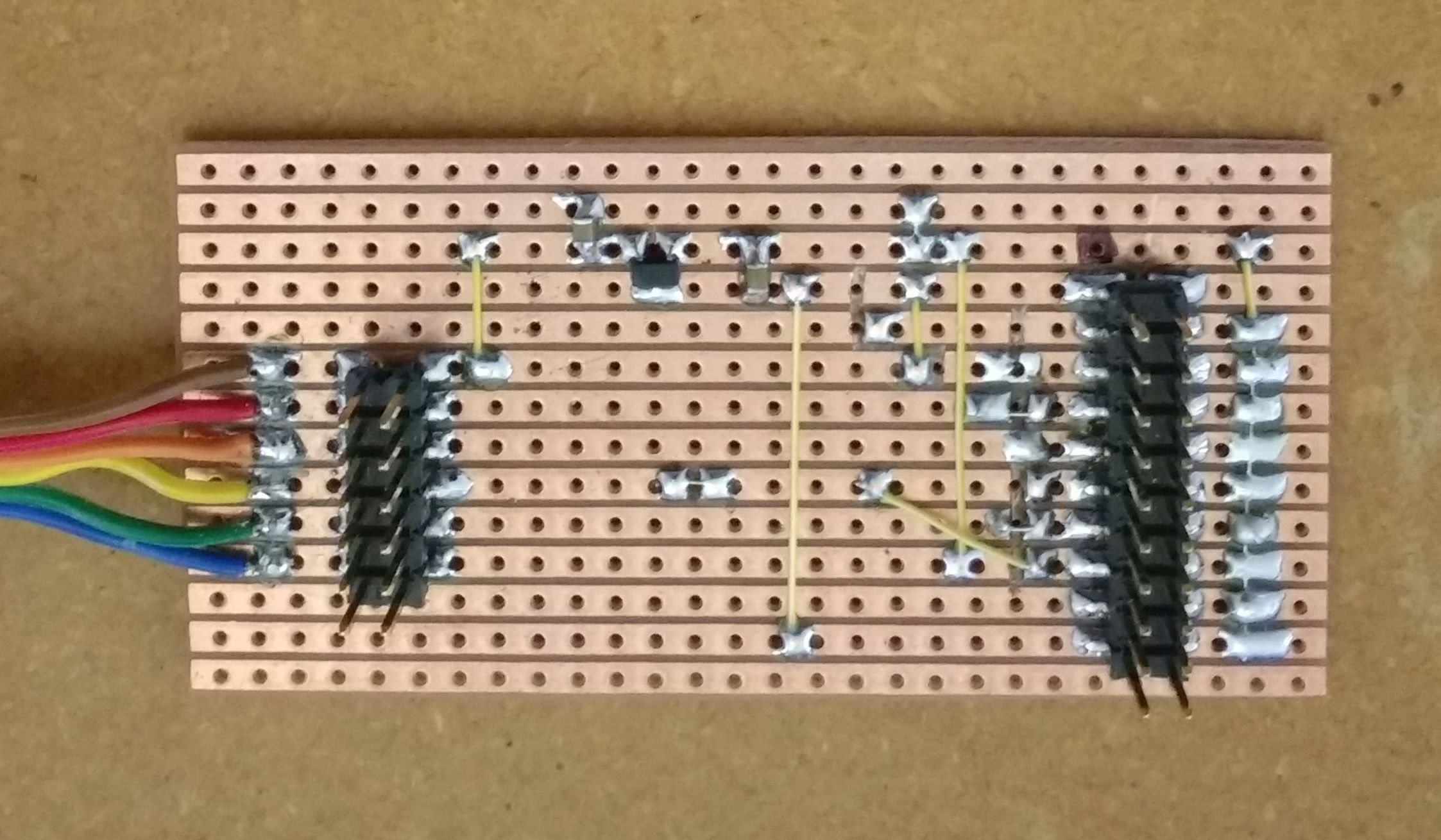
5 January 2017 Bought a Segger JLink Edu USB programming adapter. Built a JLink connector adapter for SWD configuration on veroboard to link the JLink connector to my BL652 adapter board. I was able to upgrade the BL652 module from 28.6.1.2 to 28.6.1.4 without any problems. Before running the Laird JLink Firmware Upgrade application I had to use the JLink Commander application with command Power On to enable the JLink 5 volt output. BL652 JLink Adapter Schematic:
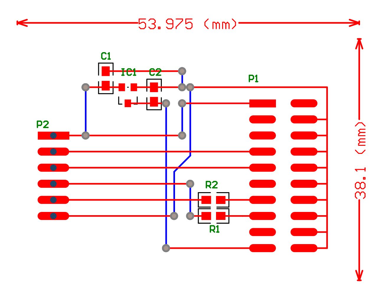
BL652 JLink Adapter PCB Layout to check on size:
BL652 JLink Adapter on a piece of veroboard:
31 December 2016 Revised the schematic and PCB to include a 5V to 3.3V LDO regulator. One less item required on the breadboard!
28 December 2016 Downloaded a couple of prebuilt apps for the BL652 from Laird. Compiled, loaded and ran the apps without any problems.
27 December 2016 Tried to upgrade the BL652 firmware by UART, from 28.6.1.2 to 28.6.1.4 but the process failed to synchronise. In a search of the internet I found that some users of the BL600 had similar sync problems, but no resolution emerged. Sent off an email to Laird for help. Interesting thing is that UART UwTerminalX still accesses the BL652 and allows AT commands, compiling, loading and running SmartBasic programs.
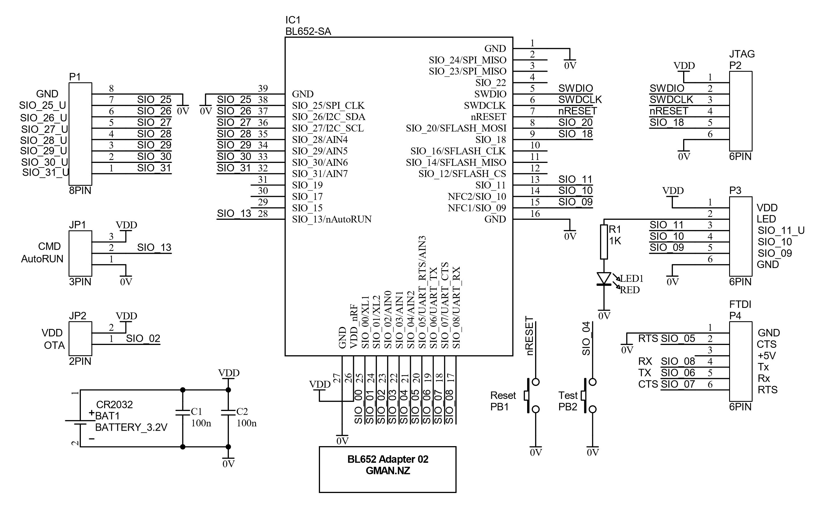
24 December 2016 Surprise! Received the BL652 modules from Mouser on 19 December. They were ordered on 10 December. Received my BL652 Adapter boards from Elecrow. Ordered 9 December, shipped 15 Dec and received on 23 December. Assembled an adapter board. Got the serial port wiring correct. :-) Used an FTDI USB cable and UwTerminalX, Com 3, 115200, 8,n,1,CTS/RTS. First AT command shows 00. AT I 2 shows 10 2 BL652. AT I 3 shows 28.6.1.2. Various AT I numbers range from 0 to 65535. Had a look at Bluetooth on my phone and can see Laird BL652. My first BL652 adapter schematic... Revision 02:
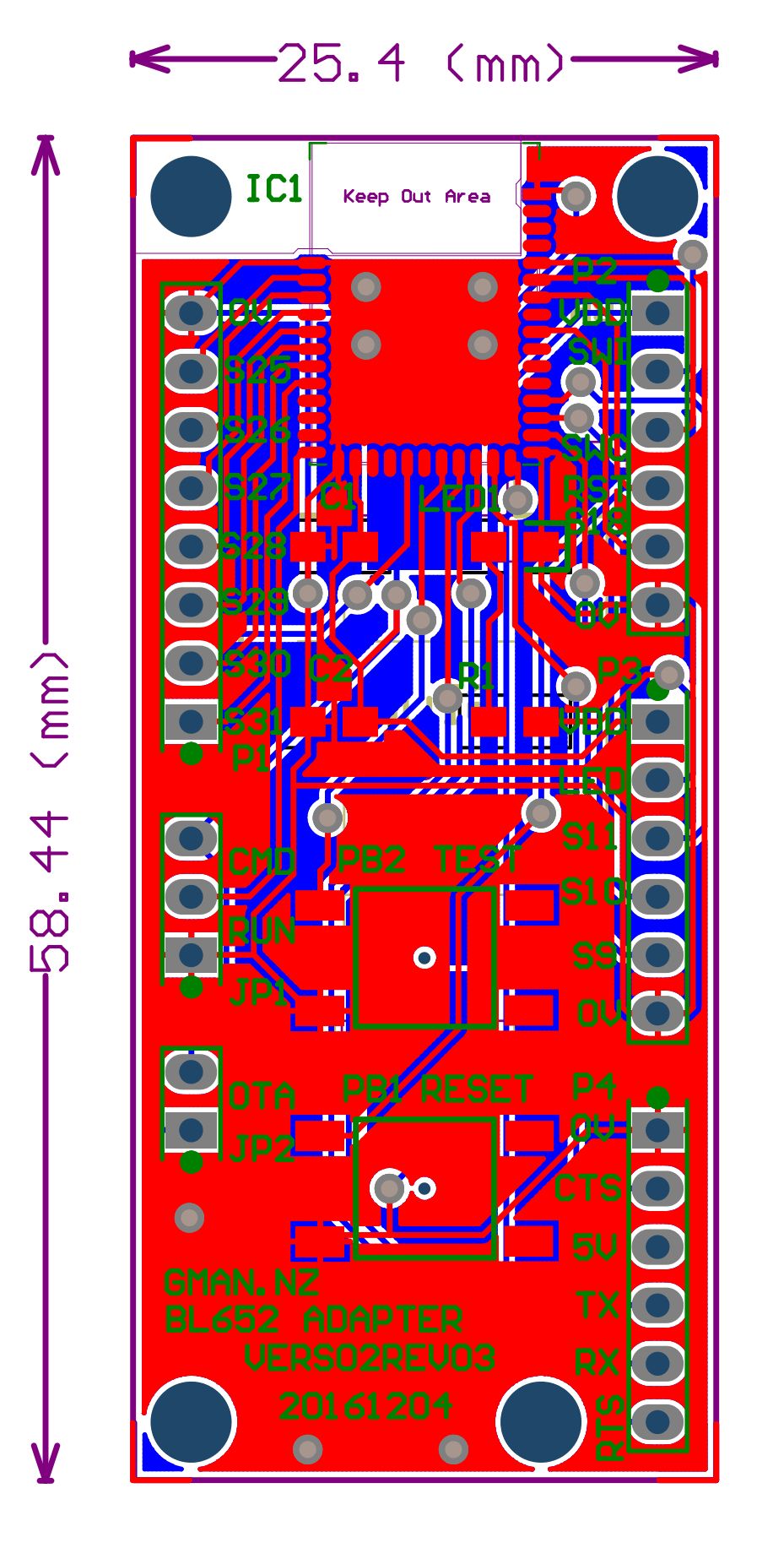
My first BL652 adapter PCB... Revision 02-03
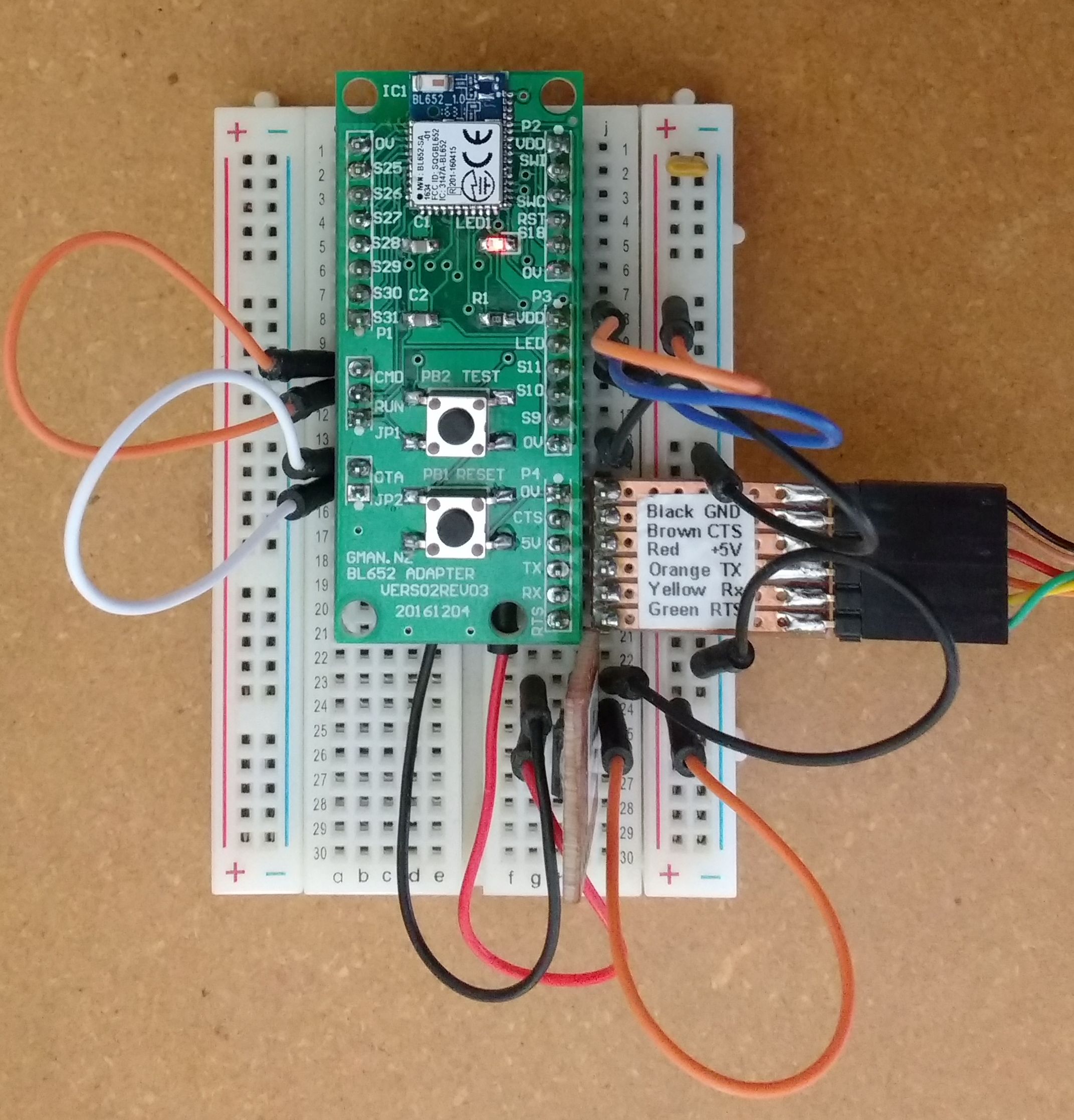
Put the adapter on a breadboard and to my surprize it works.
15 December 2016 Advice from Mouser today... BL652 modules expected to be delivered 22 December. That is fast processing! Advice from Elecrow today... My BL652 Adapter boards being are being airmailed today and expected to arrive 22 or 23 December!
11 December 2016 Found and ordered some BL652-SA-01 modules at http://nz.mouser.com/ with only a 4 week delivery.. Began looking at some Smart Basic code. Lots to learn about Bluetooth code requirements and processes!
9 December 2016 Created gerber files from my Protel PCB files. Ordered my BL652 adapter boards from elecrow.com
4 December 2016 Created schematic and PCB and required symbols and footprints. Looked for some BL652-SA-01 modules... prices about NZ$12.50 plus gst... but it seems there is a 17 week delay before they will be available.
28 November 2016 Started looking for info on the new BL652 module. Created this web page
|