|
DIY Atomic Clock using GPS Time. MicroChip PIC12F1840, PICkit2 programmer, GCBasic compiler, Adafruit 0.56" LED display with HT16K33, GPS GY-NEO6MV2.
This project was inspired by: - A 14 year old American Muslim school boy who was arrested for making a clock - which teachers thought was a hoax bomb. see http://www.bbc.com/news/world-us-canada-34266389 - My mains time-based bedroom clock that would not keep very good time because of poor or noisy mains. - Continued learning about electronics and microcontroller programming. - Understanding I2C and serial communication in the Microchip PIC 12F1840.
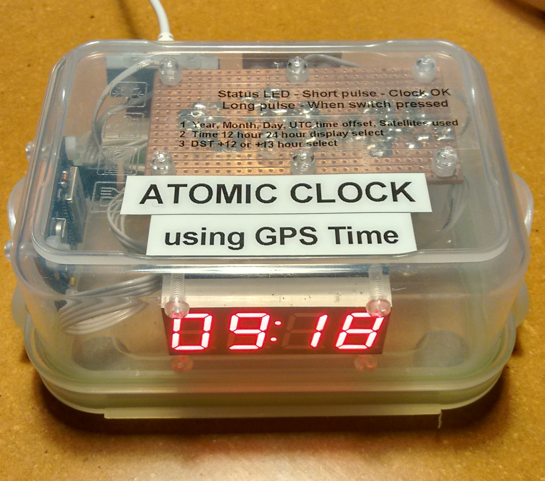
The finished clock:
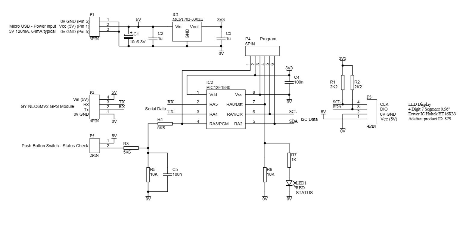
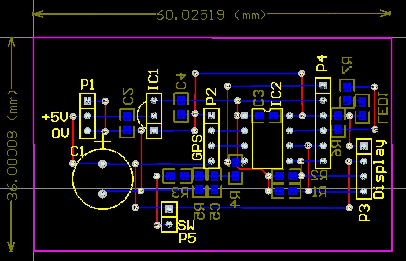
Clock GPS Schematic:
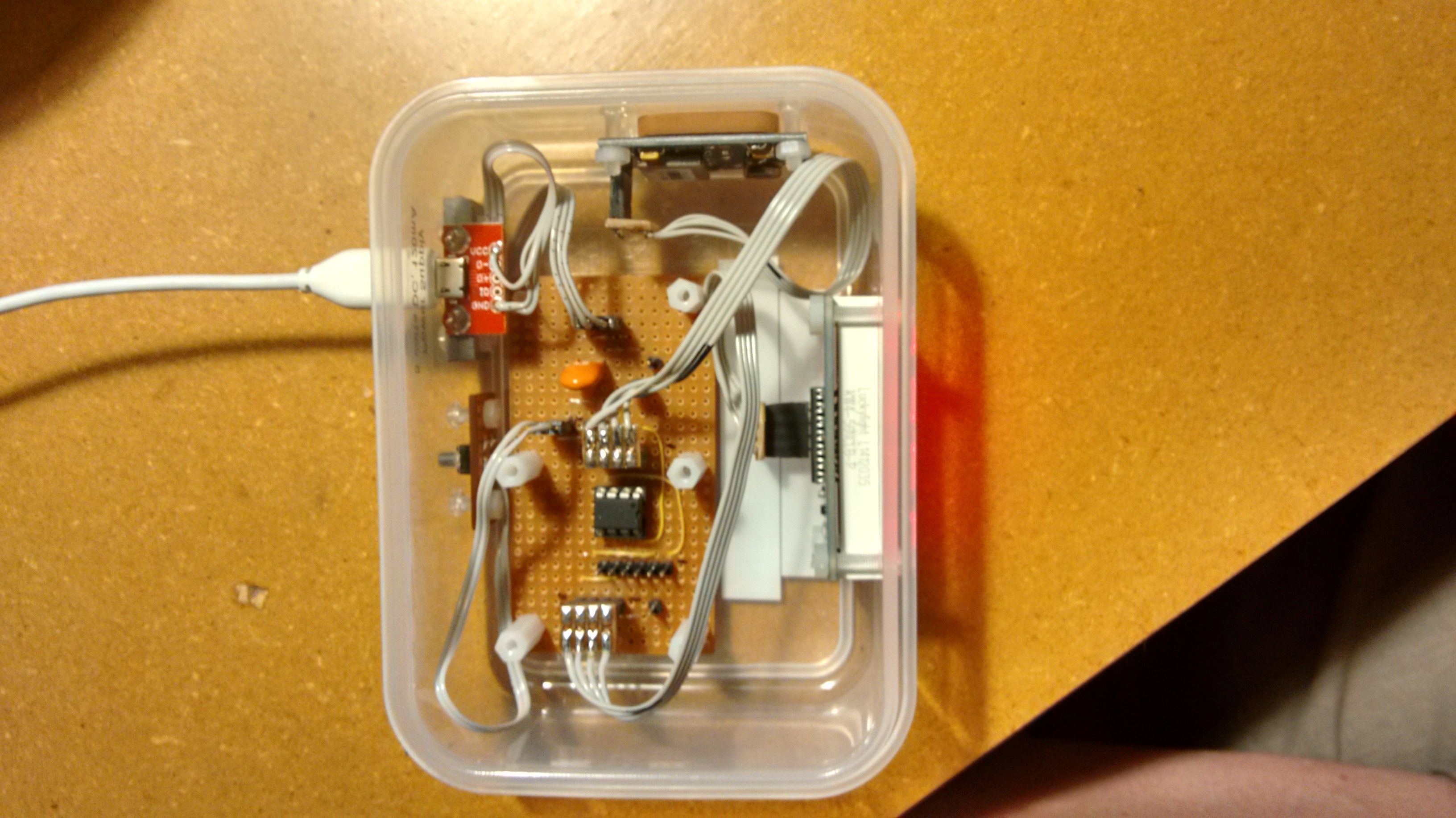
Assembled Clock:
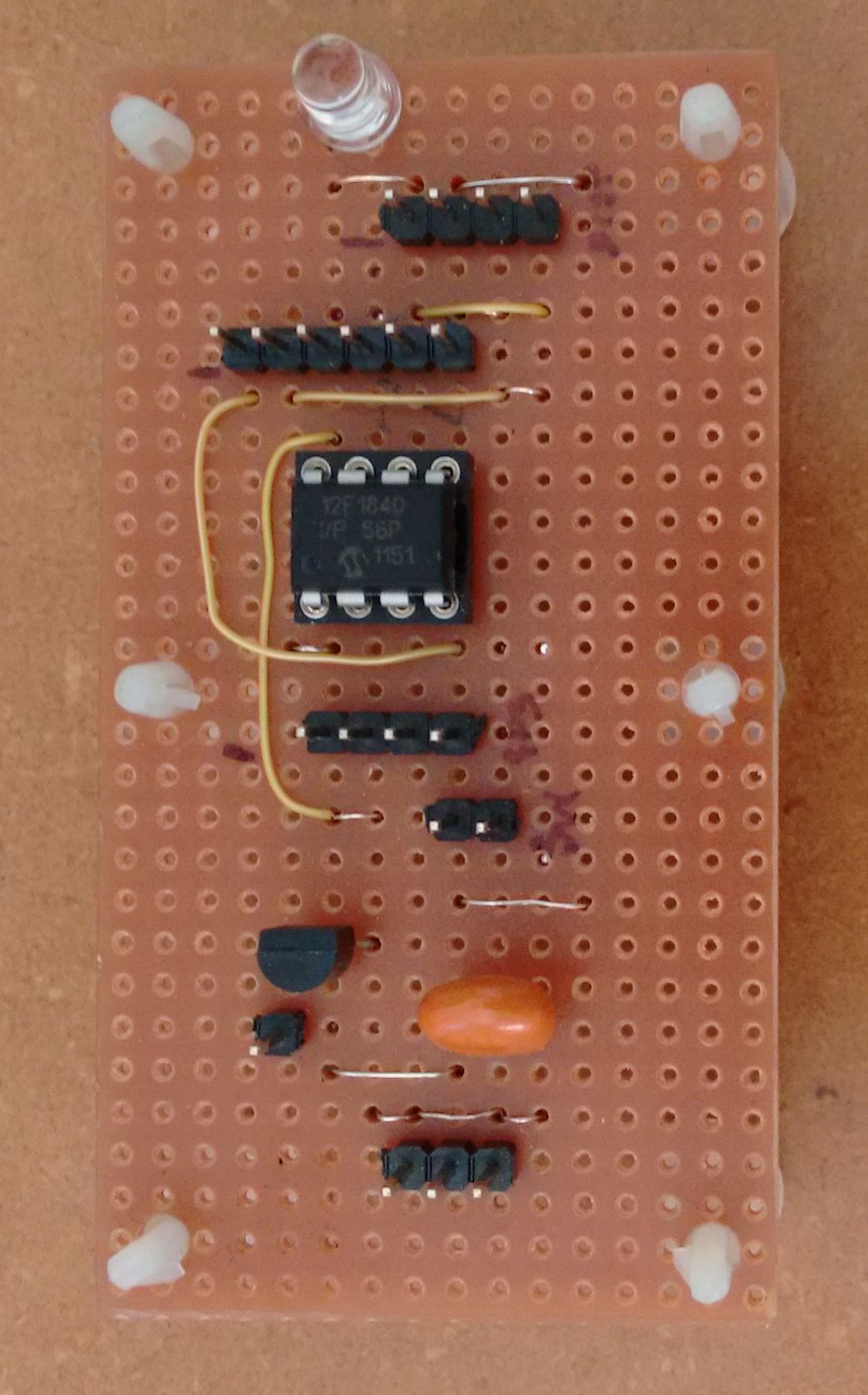
Circuit board with PIC 12F1840:
Rough PCB layout for sizing:
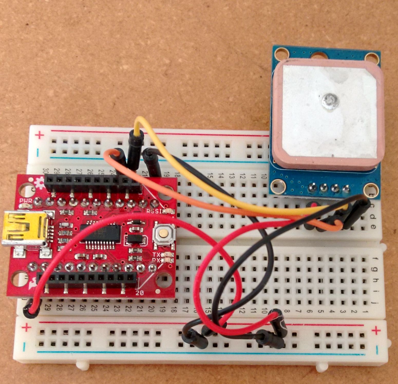
GPS module serial tests:
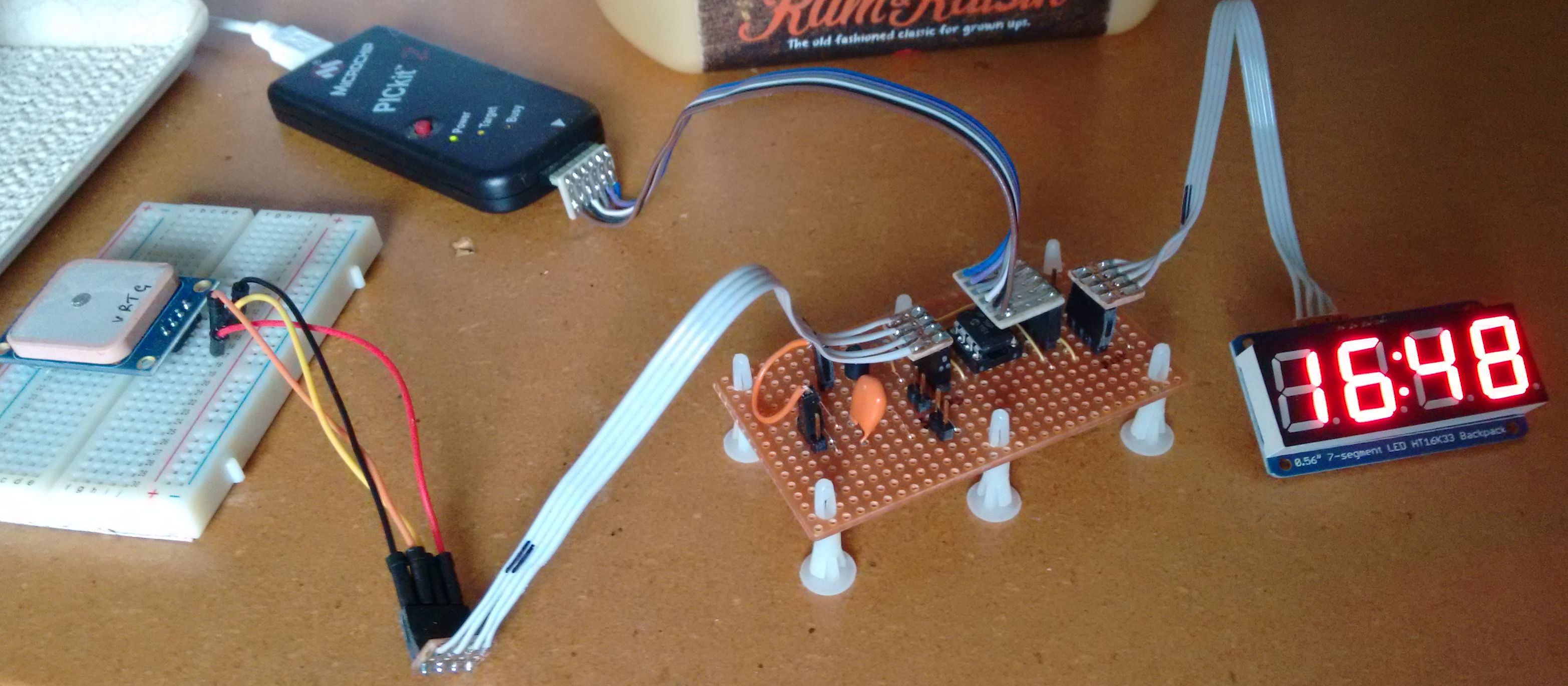
The development setup:
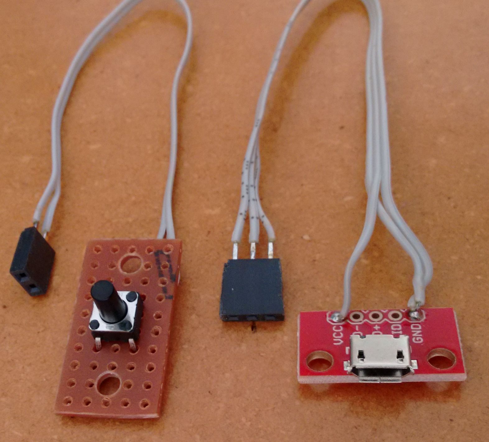
Switch and power boards:
Specification Uses time and date obtained from GPS satellites which derive their time from atomic clocks. Display: 4 digit 7 segment RED LED showing hours and minutes. Default 12hr display with 24hr display selected by push button. NZST or NZDT selected by push button. Setups of 12/24 hour display and NZDT/NZST recorded in EEPROM for recovery after power drop out. Time obtained from GPS satellites using GPS module GY-NEO6MV2. Central microcontroller using a Microchip PIC12F1840. Program code written with GCBasic compiler - powerful, flexible and easy to use. Powered from a 5 volt mains adapter with a micro USB connector. In situ programming via a 6 pin header. Push button allows reading of status: UTC Year xxxx, UTC month 1 to 12, UTC day 1 to 31, UTC time offset (NZST=12, NZDT=13) and satellites used.
Start of project 21 September 2015 Decided on project concept based on internet searches. Created a schematic. Ordered some components, Display Adafruit 0.56" (HT16K33 IC driver), GY-NEO6MV2 GPS module, MCP1702-3302E 3.3 volt regulator, various capacitors. Already had on hand PIC 12F1840 ICs, PIC programmer, vero strip board, various pin headers, SMD resistors, etc.
29 September 2015 Created this web site.
12 October 2015 I2C working to display Serial working from GPS module. GGA and RMC GPS strings used to obtain UTC, date and satellites used. DST added to obtain local time.
14 October 2015 Clock fitted to a small snack box. More software still to do :-)
20 October 2015 24 to 12 hour conversion. DST arrays created to 2051. Decided to abandon DST calculations and array lookups and use KISS and use push buttion change between NZST and NZDT.
23 October 2015 Sorted out a bit of incorrect code for local 24 hour time display. Added a display dimming feature. Display dims between 2200 and 0600. Maybe finished :-) Removed programmer cable and now the clock is powered from a 5 volt micro USB power adapter.
26 October 2015
Clock GPS 03 Display test 12F1840 I2C direct addressing was early testing of I2C communication with the 7 segment display. Clock GPS 04 Display test 12F1840 I2C rolling addressing was improved I2C understanding Clock GPS 17 12F1840 Local Time is my working clock. |

![]()


![]()
Clock - GPS