
![]()


![]()
DIY TV Remote, Timed Mute, MicroChip PIC12LF1840, PICkit2 programmer, GCBasic compiler, GCBasic, TV LG 65UN8160PVA, TV LG 55LD650.
This project was borne from a dislike for TV adverts.
TV advertising volume compression and perceived increased loudness is very annoying to me because it interrupts the mood of the desired program.
New Zealand TV advertisers are no longer allowed to use volume compression, but information compression is still very annoying and very different to the program material I want to watch.
In New Zealand on the Freeview channels there is something like 12 minutes of program material followed by 4 minutes of advertising.
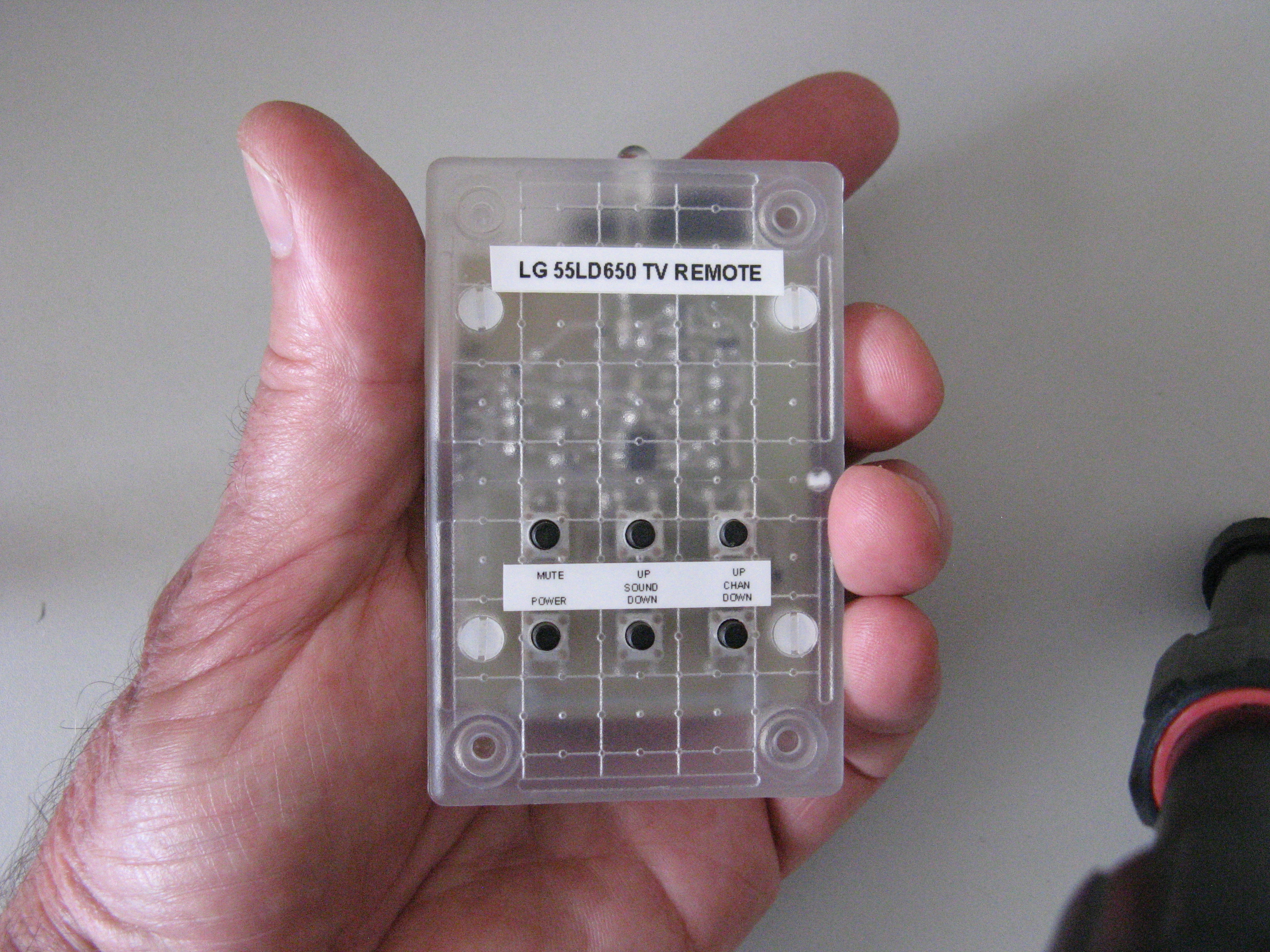
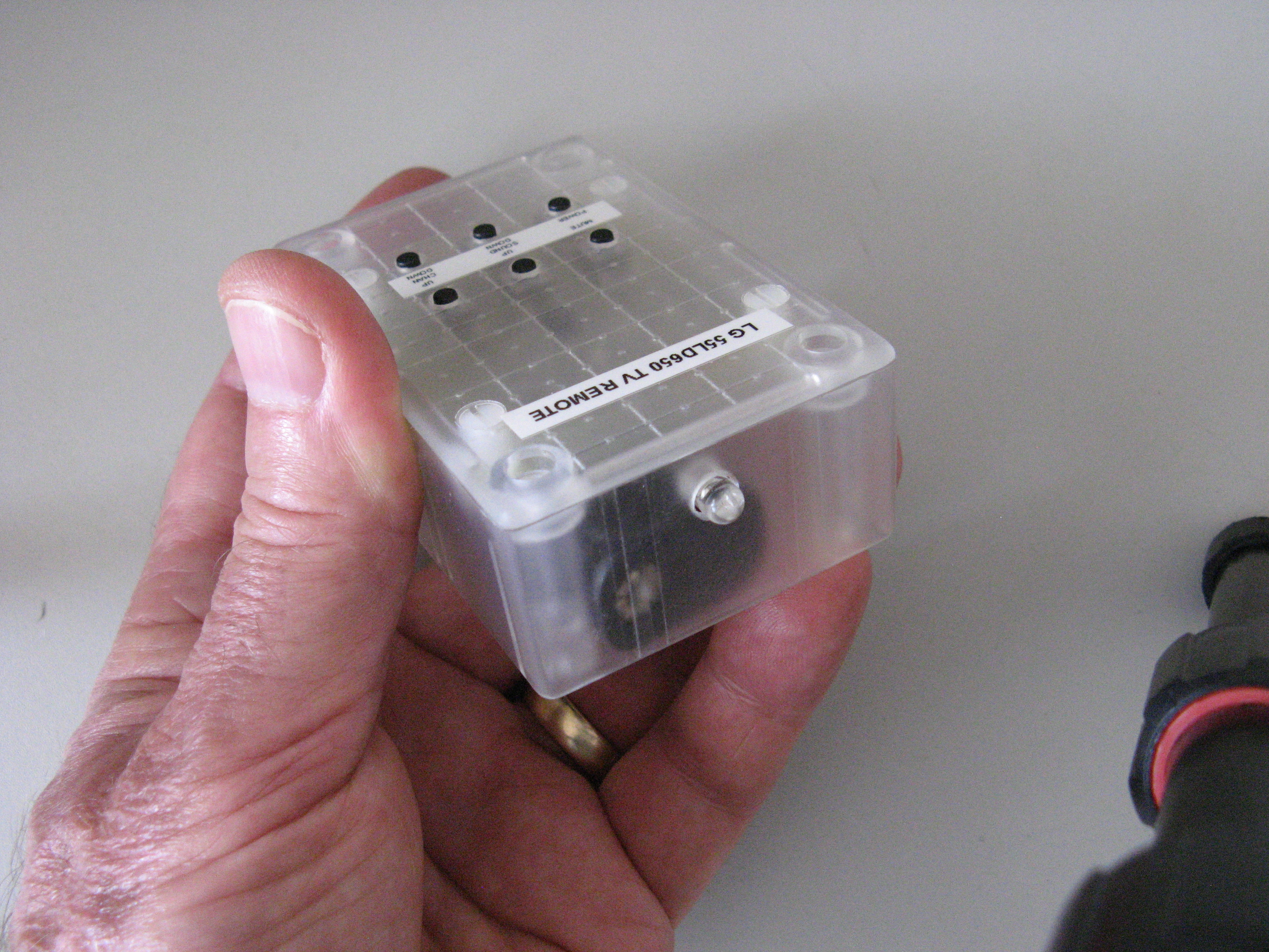
My TV Remote:
The birth of a specification:
A simple remote that would mute TV sound for a set period of time, 4 minutes.
The spec evolved:
Mute/Unmute short press.
Mute/Unmute by long press >1.5sec. Mute for a timed period. Initially 4 minutes.
End timed mute and set new end of time period.
Extend mute timer period by 30 seconds for up to 10 seconds before timer period ends.
Power ON/OFF Sound Up/Down. Channel Up/Down LEDs for status
Powered from 3V by 2x AA batteries.
Low standby current.
Reverse battery protection.
Total reset to default Mute Time by pressing Power and Channel Down at the same time.
The TV hardware:
TV LG 55LD650 The user manual gave a list of IR codes The more difficult part was finding the IR address. The TV set ID was not what is used for IR address. Found 0x04 as IR address.
As of June 2020 the IR code has been revised to suit an LG 65UN8160PVA TV.
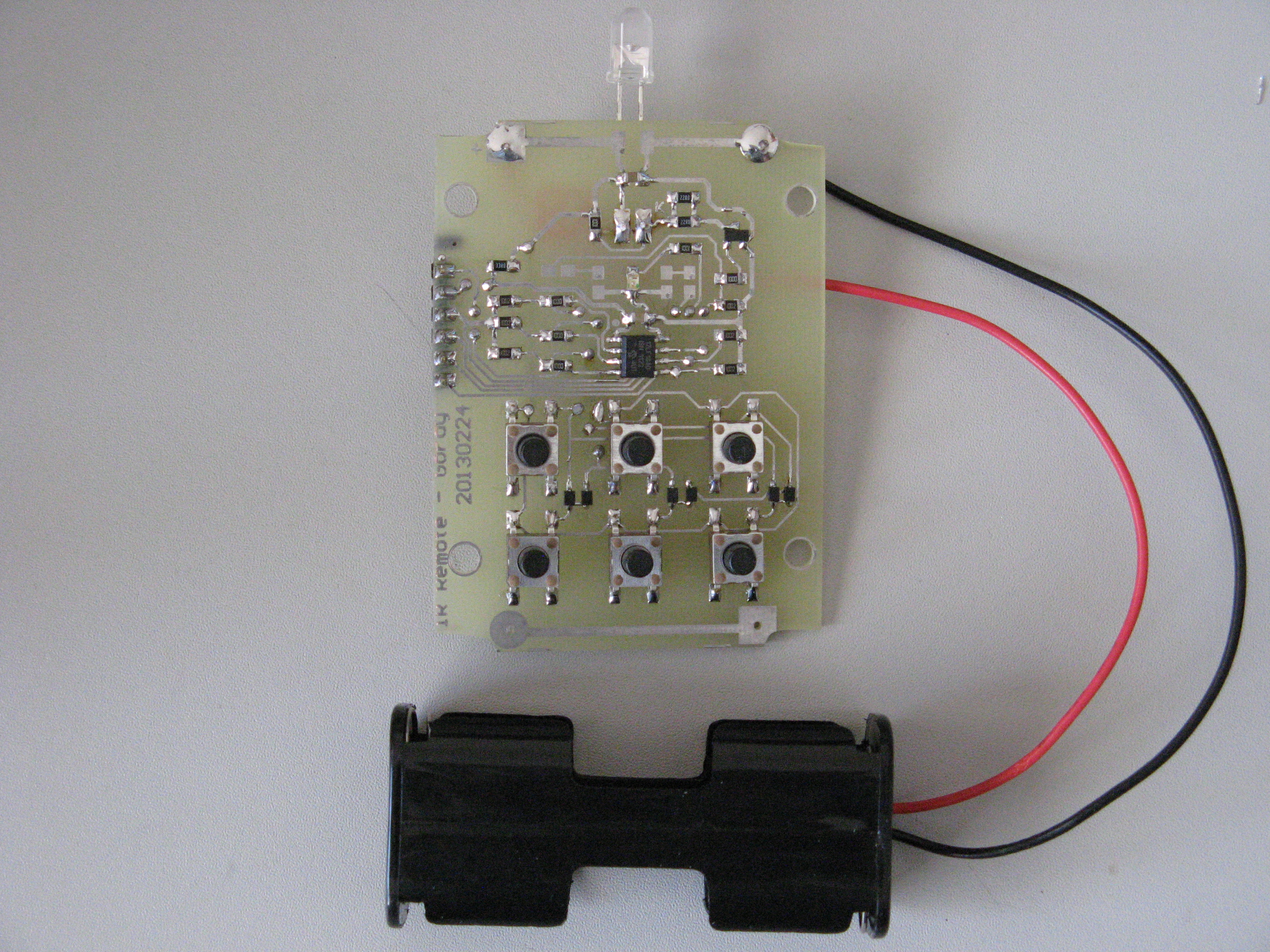
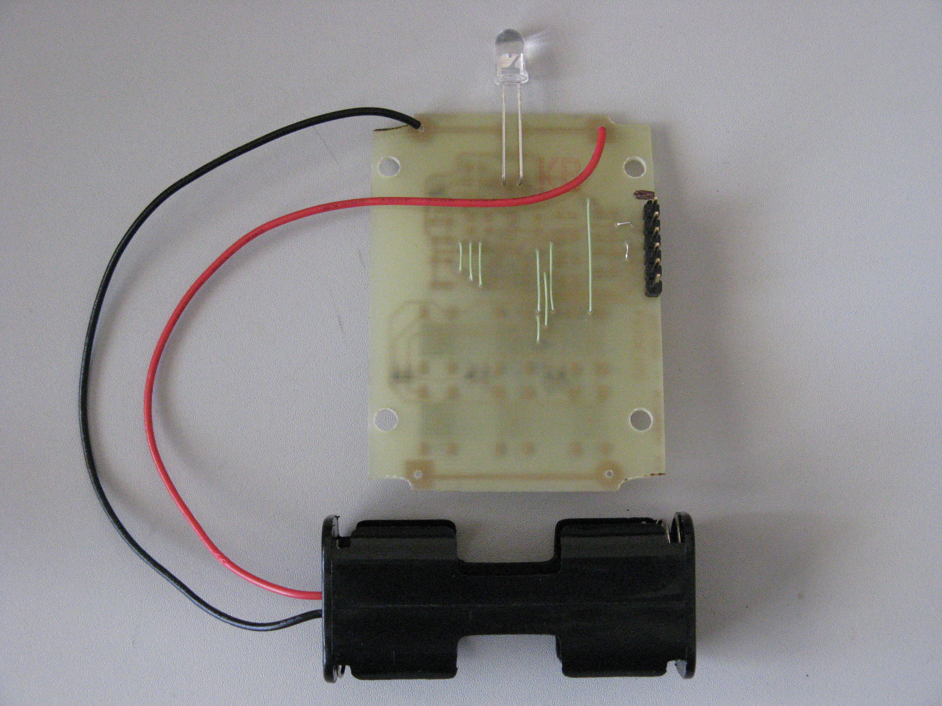
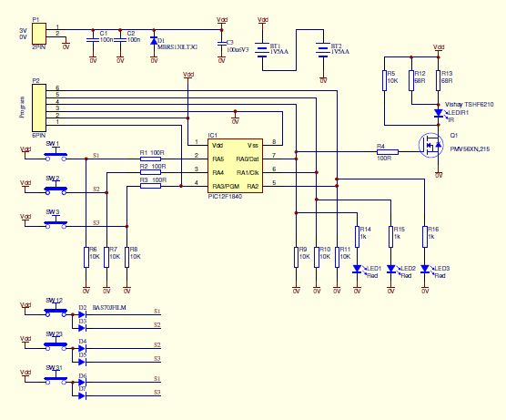
Remote hardware
PIC12F1840 A fairly new chip with enhanced features. Data Signal Modulator with On-Off Keying seemed very suitable for the IR Remote application. Available in DIP8 and SOIC8, with 7kB or program memory and costing a little over NZ$2 per chip... ideal.
Data sheet is a mammoth 410 pages... Awesome
Software/Firmware:
Written with GCBasic compiler.
This is a nice structured Basic for PIC and AVR microcontrollers. Produces assembler, list and hex output files.
The assembler and list files are very useful for debugging and understand the code that GCBasic produces.
The hex file is used by the programmer.
Programmer:
PicKit2 from Microchip.
This proved to be very useful, not only for programming the PIC microcontroller but also as a 3 bit logic analyser.
In preparation for selling my house I also sold my oscilloscope.
The PICkit2 logic analyser allowed me to see and measure the timing of the IR data stream.
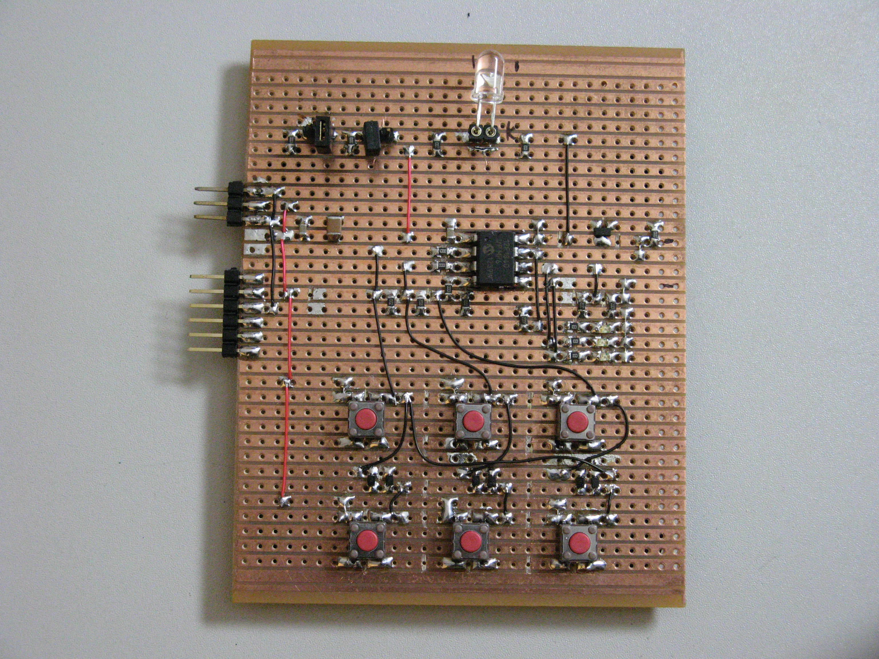
The prototype:
I created a schematic and did a PCB layout for feasibility and sizing. I constructed a Veroboard (stripboard) prototype.
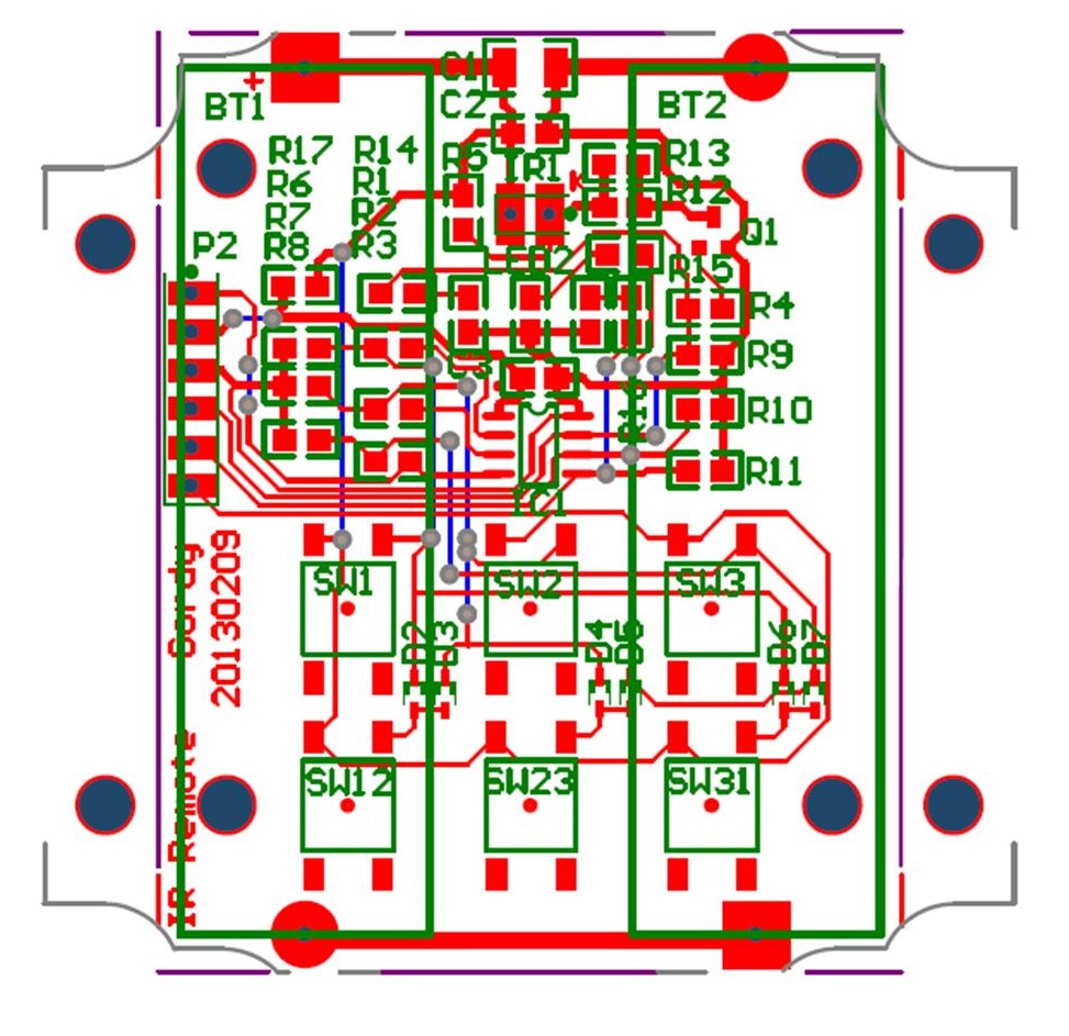
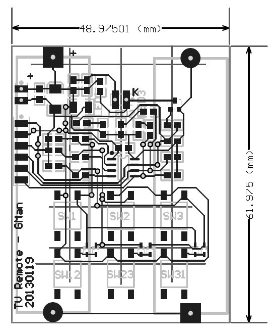
The PCB:
I did want to make this a single side PCB with all SMD components on the top side, battery holders and IR Led on the bottom side. I ended up with 11 links (or it could be a double sided PCB).
Progress:
20121214
Started schematic, selected components and ordered, built veroboard prototype, created first PCB layout for feasibility.
20130107
IR command tests done.
IOC (Interrupt on Change) switch tests underway.
Switch debounce tests and improved IOC tests underway.
20130127
Switch IOC and debounce working well. All buttons sending IR commands.
Some command timer tests done. Some GCBasic timer interactions with DSM PWM ironed out.
Code pretty rough in places.
Standby battery (3V) current is 13uA without configuring the microcontroller low power mode.
20130209
Disabling internal regulator did not reduce the 13uA. The regulator probably not active anyway with a supply of 3V.
Data on 100uF 6.3 V multilayer ceramic capacitors shows leakages of 6 and 12uA. These leakage figures are at high temperature.
Removed the 100uF from circuit. No change in current. Disabled IR FET with no change of current.
Added code to make sure microcontroller disables analogs, comparator, DAC, Vrefs, pullups, timer1, capacitive sense module, etc.
No change of current. Running the microcontroller at 16MHz internal. CPU clock is shut down during sleep.
Modified the circuit to provide better reverse battery protection.
PCB layout pretty much finalised and made to fit two different box options.
Range tests over 15m at 3V.
Timed mute fixed at 4 minutes with early switch breakout. More work needed.
20130210
Erased the chip. Battery current now 273uA. Reprogrammed the chip...back to 13uA. Need to socket the chip to check the PCB current without a chip and to install another chip. Plan to get some high value resistors to check the calibration current of my meter.
20130213
Haven't got the Sleep current down to low levels.
Board without microcontroller draws about 0.4uA.
I will try and reduce the board current after I have the Sleep issue sorted out.
The board with PIC12F1840 I/P MP6 1239W, current 13.2uA This is a DIP8 chip.
Tried a second DIP8 chip also from the same batch, Current 12.5uA
Tried a SOIC8 chip 12F1840 ISN 1242 C30, current 10.2uA. Checked the external 10K pull downs are at 0V
Before Sleep my code changes I/O to inputs, disables pullups, ADCs, comparator, DAC, Vrefs, timers 1 and 2 and Cap sensing.
Configs select internal osc and disable WDT, BOR, MCLR and Clkout.
Have been using a PICkit 2 programmer and now going to get a PICkit 3 so I can have a closer look at the SFRegisters.
My program code runs ok, but I now want to find out why the chip draws more current than expected in Sleep.
The 12uA suggests that I haven't turned off a module in the chip.
20130302
Still trying to get the 12uA standby down. Have tested various PIC chips in standby and all are <100nA @3V
Have ordered some 12LF1840 chips to test.
20130306
Fixed a compiler issue by updating the 12F1840.dat file.
Best standby current for the 12F1840 now 3.7uA @3V.
Ran the same code in a 12LF1840 and the standby current is <100nA @3V.
I am going to use the 12LF1840 and try and finish the project.
20130307
Fixed a Sleep code program mis-understanding in the 12F1840.
12F1840 Sleep current is 100 to 200nA @3V
12LF1840 Sleep current is <100nA @3V
20130309
Completed the code last night and assembled the finished remote this morning.
20130519
I have been using the TV remote for a few months now.