
![]()


![]()
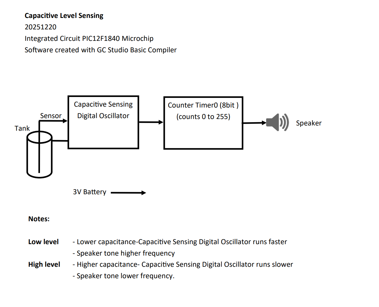
Capacitive Level Sensing
Key words: Capsense CPS Touch Sensing Capacitive Level Sensing PIC12F1840 Microchip GCBasic Compiler GCStudio PICKit 2 Serial Debug
My project started with this spec for a fuel level teaching aid:
Is it possible to make a buzzer circuit, perhaps with a 9v battery... some sort of basic resonance that uses a coil and capacitor?
But to replace the capacitor with two parallel wires or two strips of 5mm x 100mm stainless steel a few millimetres apart... then dip the wires/strips/plates into a glass of water and listen for the frequency go up and down as the plates go further into the water, etc?
The reason I ask, is that the fuel quantity measuring systems in big aircraft and the ones here use a capacitance system.
I'd just like the students to hear the buzzer frequency change as I dip two plates into water.
22 September 2025
So - in for a challenge!
Microchip PIC12F1840 microcontroller to the rescue - my favourite chip which I have used in many projects.
Software created with GCBasic Compiler.
I was a little dissappointed that GCBasic did not have an instruction or command to access the Capacitive Sensing built into this chip.
So, I decided to write my own code.
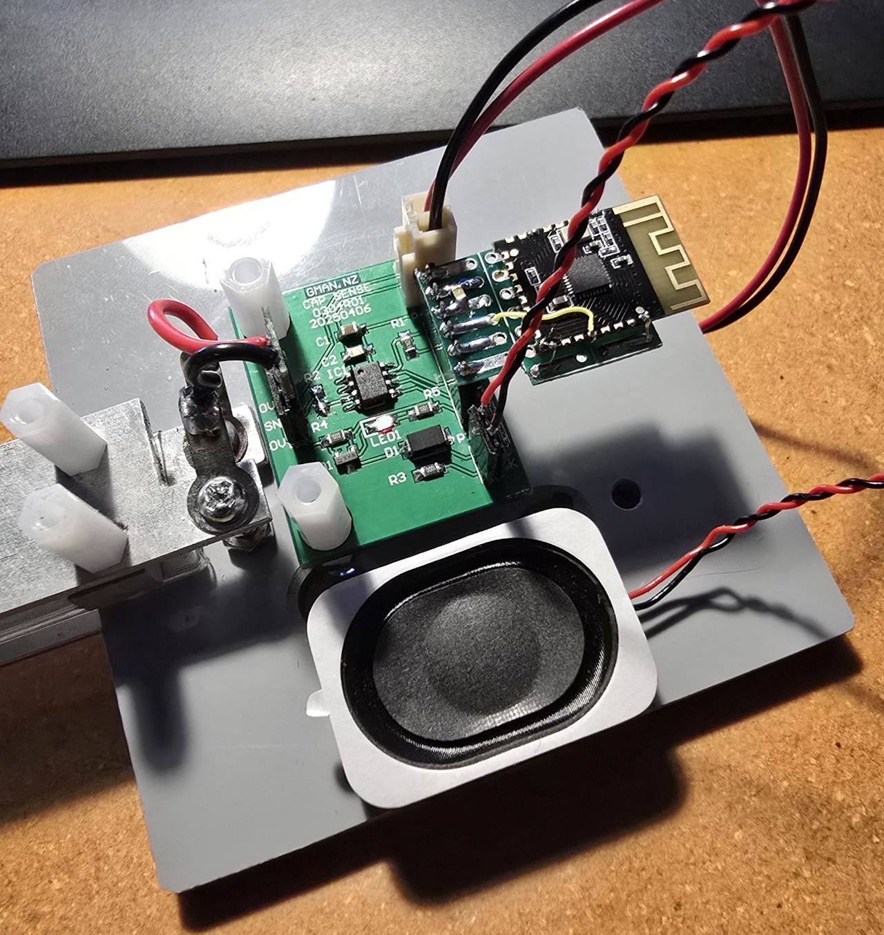
Prototype PCB:
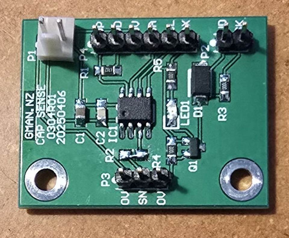
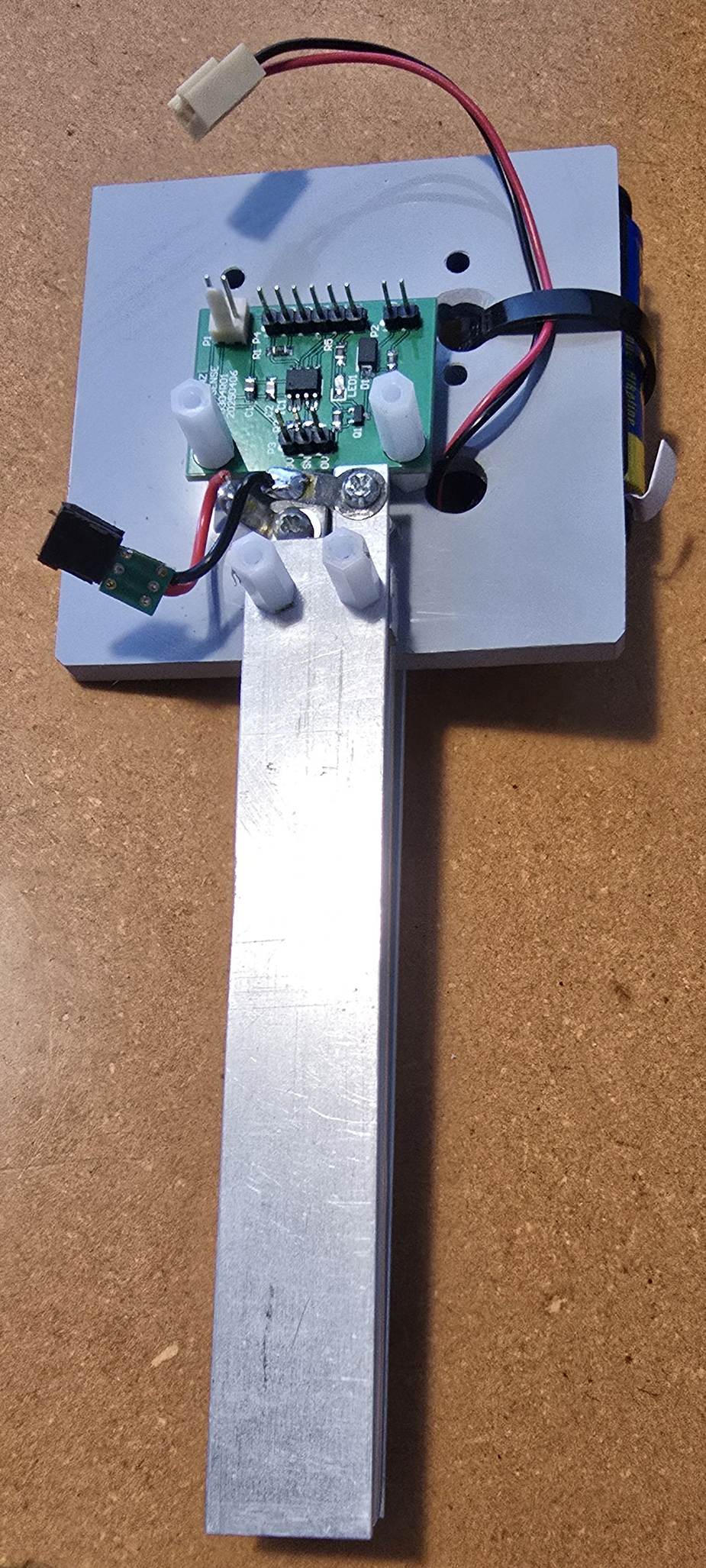
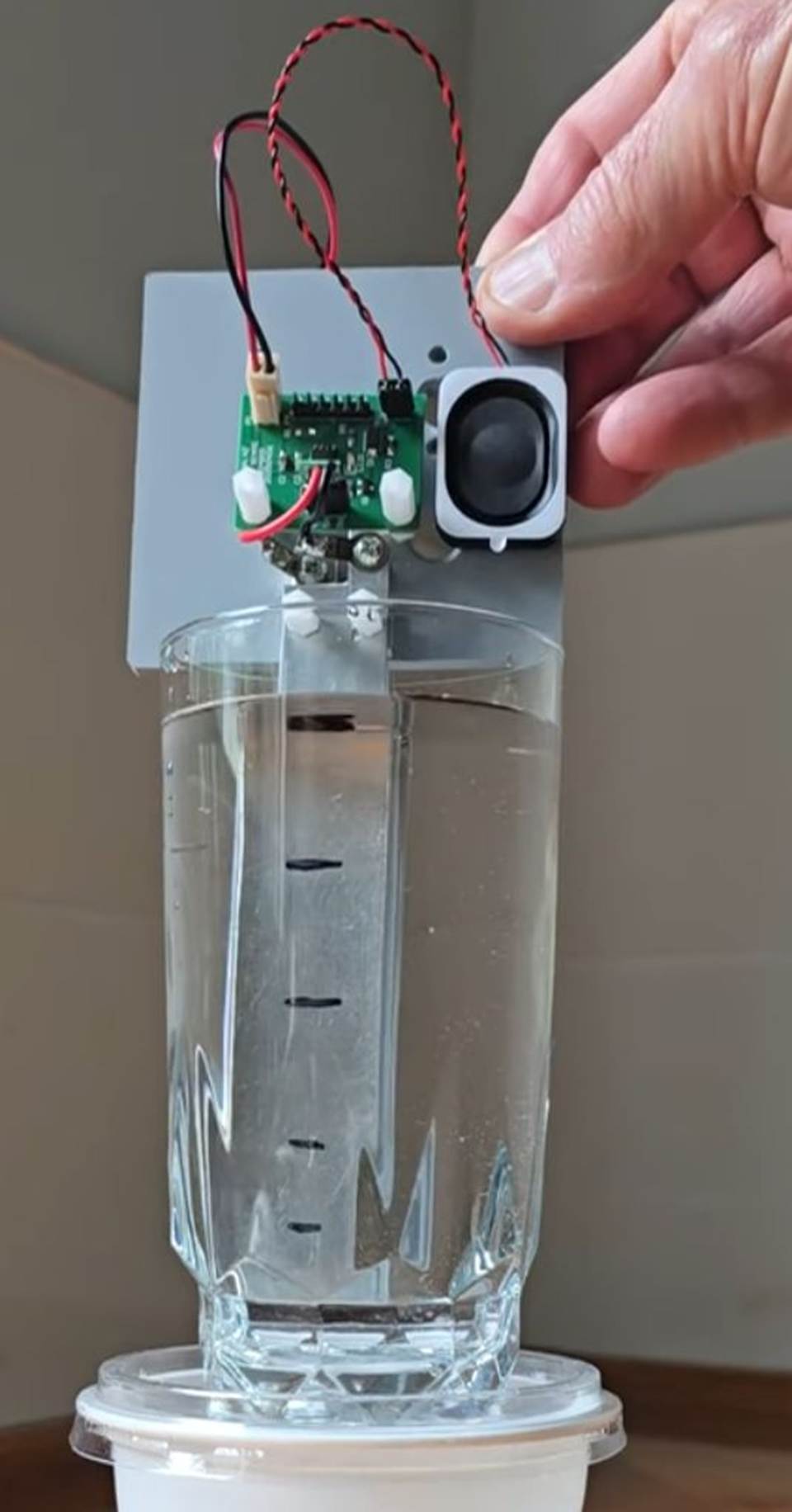
Plate assembly:
Assembly with 3 aluminium plates 120 x 20mm with spacing 6mm.
Centre plate is covered with clear heat shrink sleeving to insulate it from
water used in the demo. The outer plates provide some measure of shielding
from external influences. Plates have a capacitance of approx 200pF when
immersed in water to 100mm.
Calculated capacitance was 427pF with the plates immersed in water
to 100mm. Reduced measured results were likely because the centre plate
is covered with heat shrink sleeving.

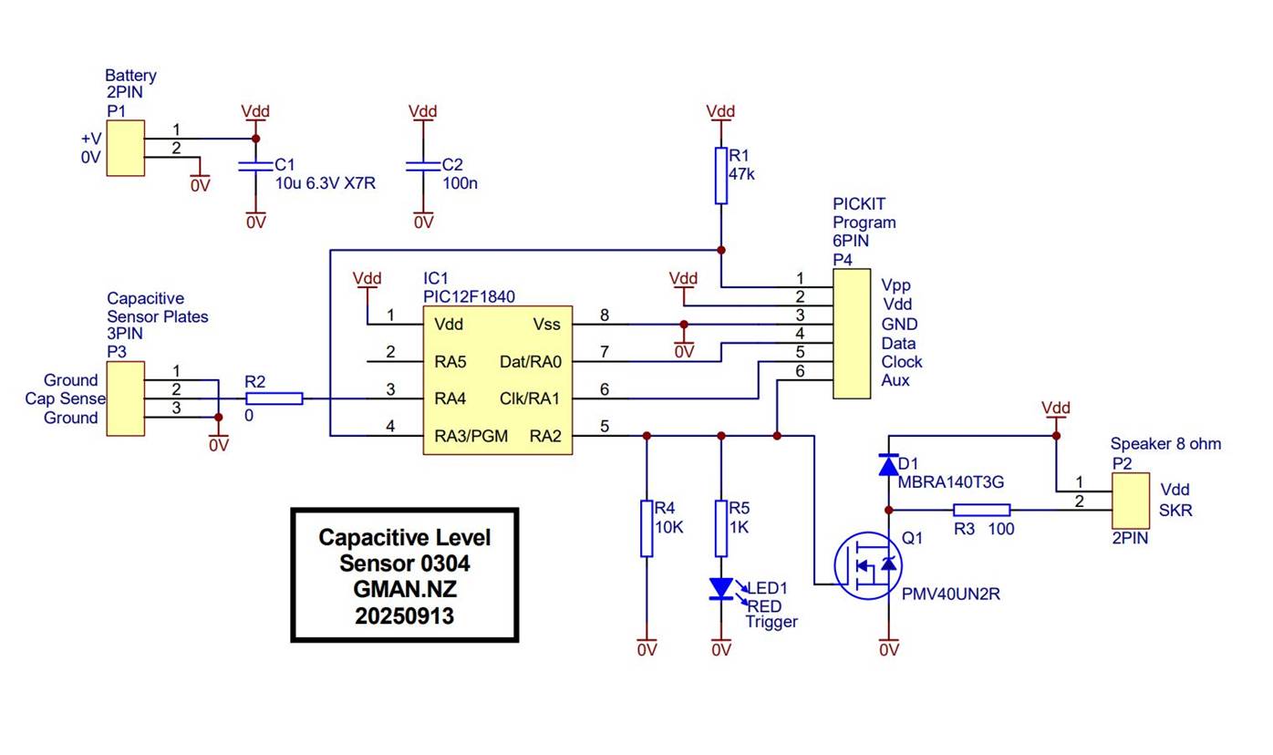
Schematic:
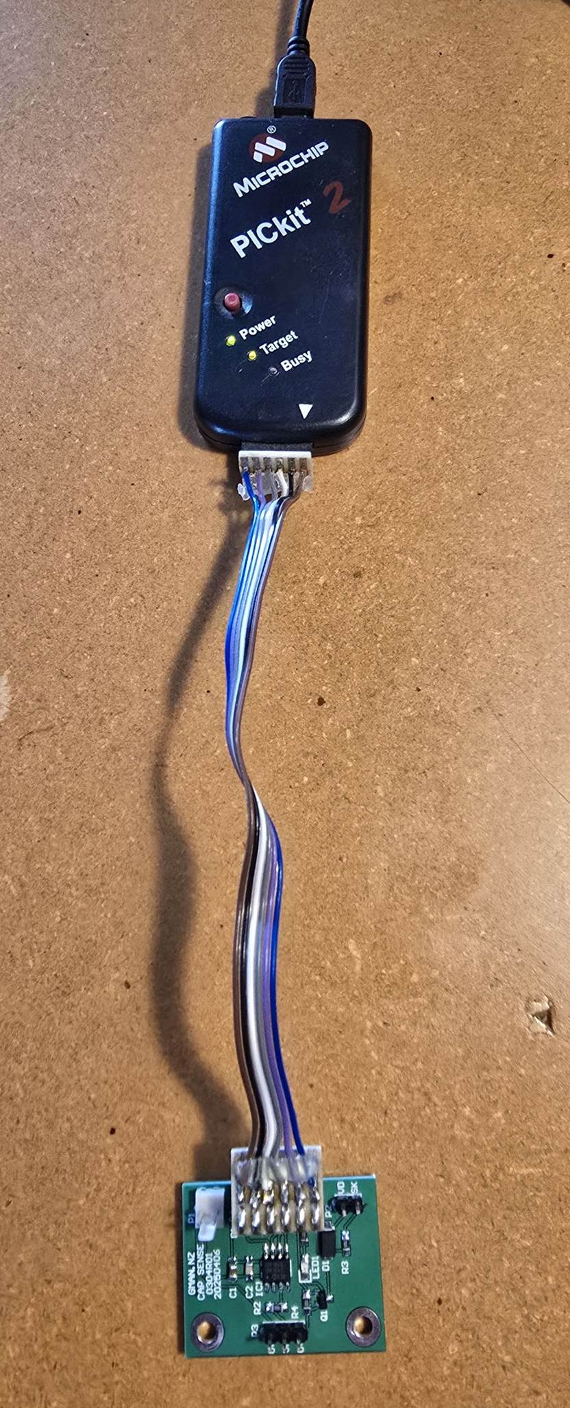
Programmer:
A PICkit 2 was used to program and debug the code as it provided serial output for monitoring data.
Trying to use a later model PICkit with GC Studio and MPLab 6.25 wasted 3 days.
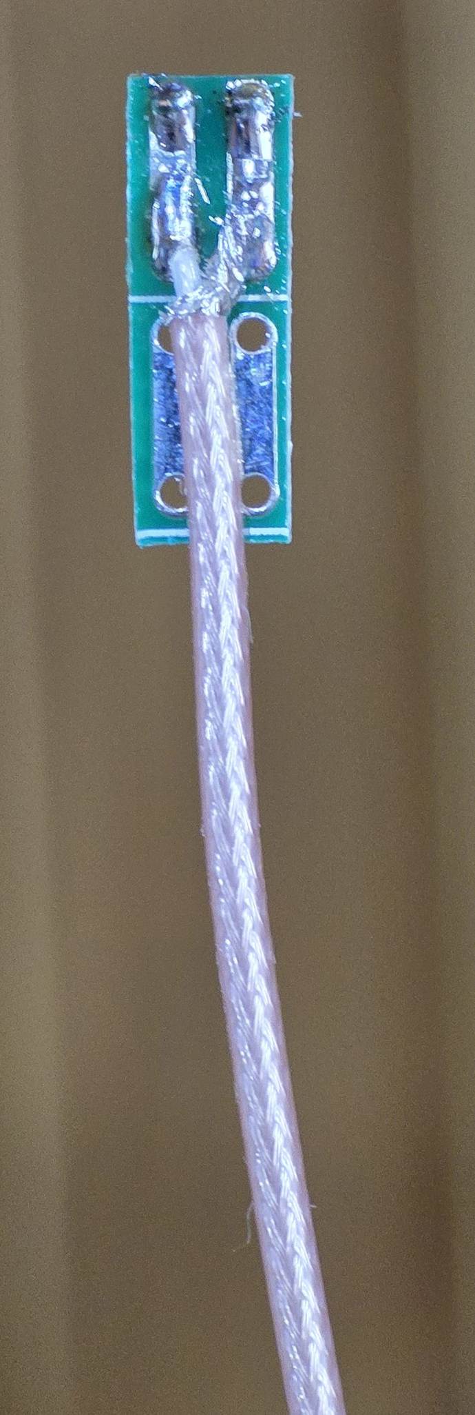
Test Capacitors:
After initial tests with water, several test cables were made using RG178 coax to provide capacitors.
RG178 has a capacitance of approximately 100pF per metre.
A 2m cable was made to represent the plates immersed in water to 100mm
Next - I am waiting for a JDY-23 Bluetooth module to arrive so that I can send data to a phone and perhaps make a bargraph display.
25 September 2025
Received my JDY-23A Bluetooth module today and tacked it on to a carrier that connects to the PIC12F1840 PCB
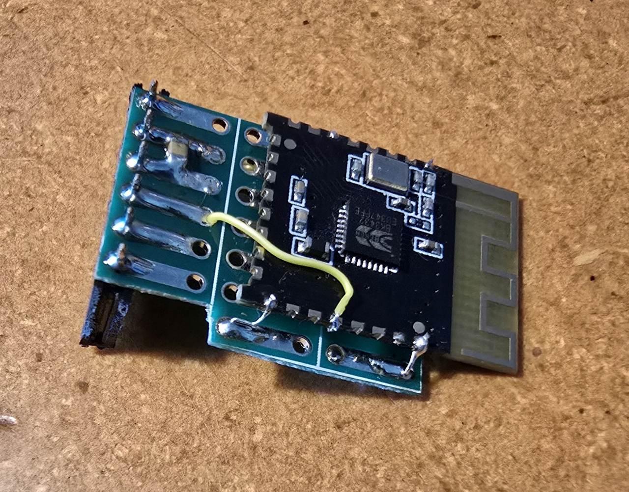
Bluetooth paired up on my Android phone without any problem. I can see my data on the Serial Bluetooth Terminal.
30 September 2025
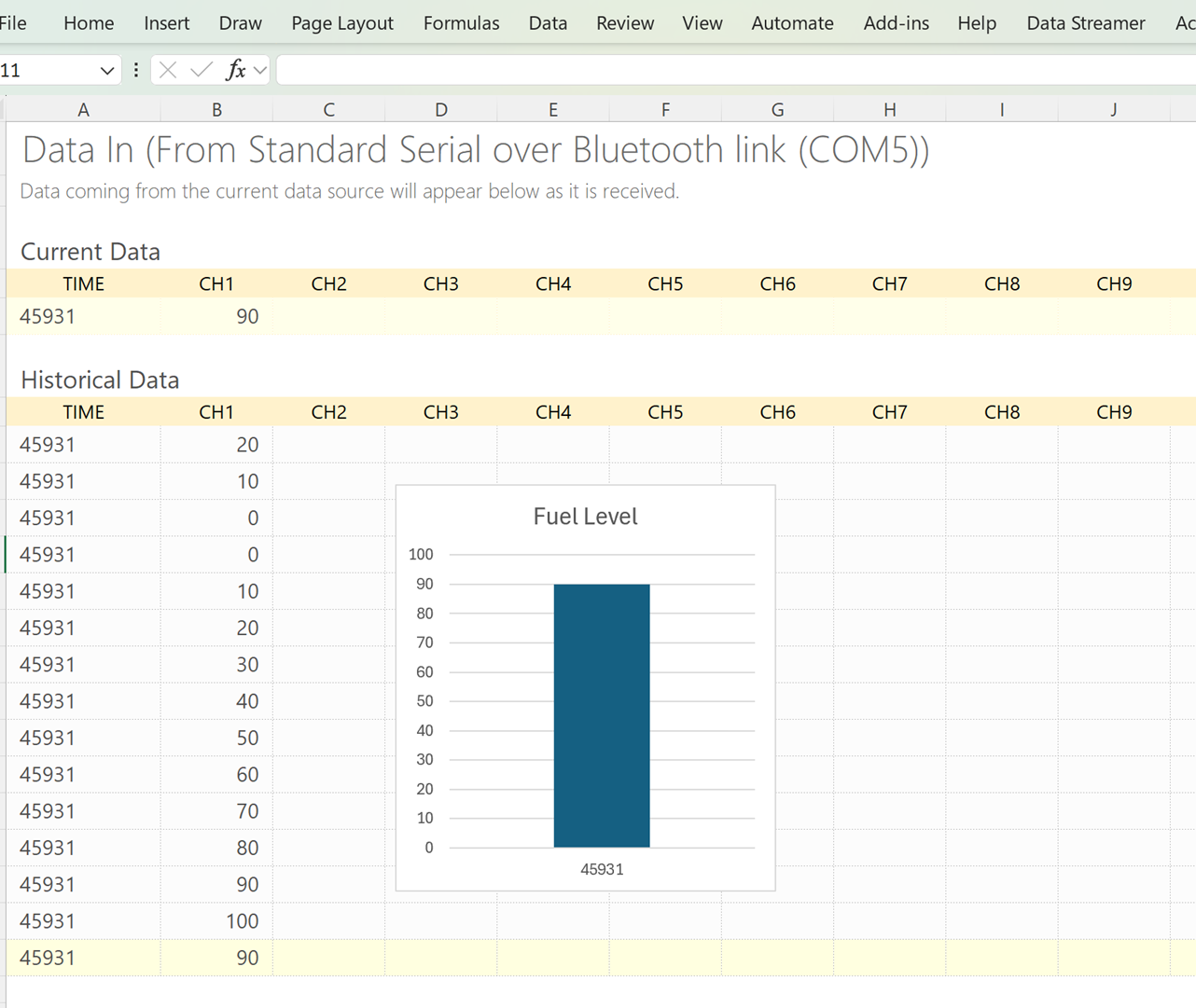
Wanted to create a Bar Graph Gauge to display my Bluetooth data.
Used MS Excel Data Streamer to capture the data and display it
See here on Youtube:
20 December 2025
Success with a simple config:
'Code written for GC Basic compiler:
;Chip Settings
#chip 12F1840,4
#config OSC=INTOSC, CLKOUTEN=OFF, MCLRE=OFF, WDTE=OFF, BOREN=OFF
#option Explicit
'
' Capsens PIC12F1840
' Capsens PIC12F1840 18 Speaker tone directly from Timer0 overflow
' 24 December 2025
'
' To use PIC12F1840 timers
' Use TMR0 to count CPSCLKs
' Use TMR0 overflow toggles speaker
'
;Defines (Constants) UART in PICKIT 2 used for debugging
'
;Variables
Dim acount As byte
'
' RA0
' RA1
' RA2 LED and SKR output
' RA3
' RA4 Capsens input CPS3
' RA5
'
'==== Main routine =====================================================
'
Start:
'
' All bits input
dir porta in
dir porta.2 out
'
' Flash LED on startup
for acount = 1 to 10
porta.2 = !porta.2
wait 100 ms
next
'
wait 1000 ms
'
CPSsetup
'
Start1:
'
TMR0=255-32 ' preload TMR0 to vary overflow period
'
CPSCON0.CPSON=1 ' enable TMR0
'
INTCON.TMR0IF=0 ' clear TMR0 Overflow flag
'
Do until INTCON.TMR0IF=1 ' wait for TMR0 overflow
Loop
'
CPSCON0.CPSON=0 ' disable TMR0
'
porta.2 = !porta.2 ' Toggle speaker output.
'
goto Start1
'
' ==== End of Main routine ==============================================
'
'==== Subroutines ============================================
'
sub CPSsetup
'
TRISA = 0b00111011 ' pin RA2 output, pin RA4 to input.
ANSELA = 0b00010000 ' CPS3 input to pin RA4
CM1CON1 = 0b00000000 ' Disable all comparator interrupts
'
CPSCON0 = 0b10000101 ' bit7 CPS enabled=1, bit6 CPSRM Fixed VRef=0, bit 54 xx, bit32 Osc Low current 01, bit1 CPSOut status, bit 0 TMR0CS clock source is CPSCLK = 1
CPSCON1 = 0b00000011 ' CPS3 - input on pin RA4
'
INTCON = 0b00000000 ' clear all interrupts
OPTION_REG = 0b11101000 ' All weak pullups disabled, Int Edge rising, TMR0CS T0CK1, TMR0SE T0CKI pin 0, PSA prescaler not assigned = 1, TMR0 prescaler = 000 = 1:2
T1CON = 0b11000100 '' TMR1CS CLK source 11=CapOsc, T1CKPS Prescale 00=1:1, T1OSCEN 0, -T!SYNC 1, x, TMR1ON 0
T1GCON = 0b00000000 '' TMR1ON gate on=0, T1GPOL low=0, T1GTM Gate Cntrl disabled=0, T1GSPM single pulse disabled=0, T1GGO/-done Status 0, T1GVAL State bit, T1GSS TMR0 overflow=00
'
end sub
'
'============================================================