Dog US Deterrent
|
Decided to build an Ultrasonic Dog Deterrent to try and control a family dog from being a nuisance.
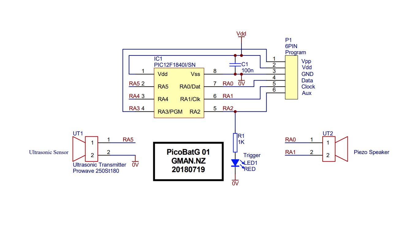
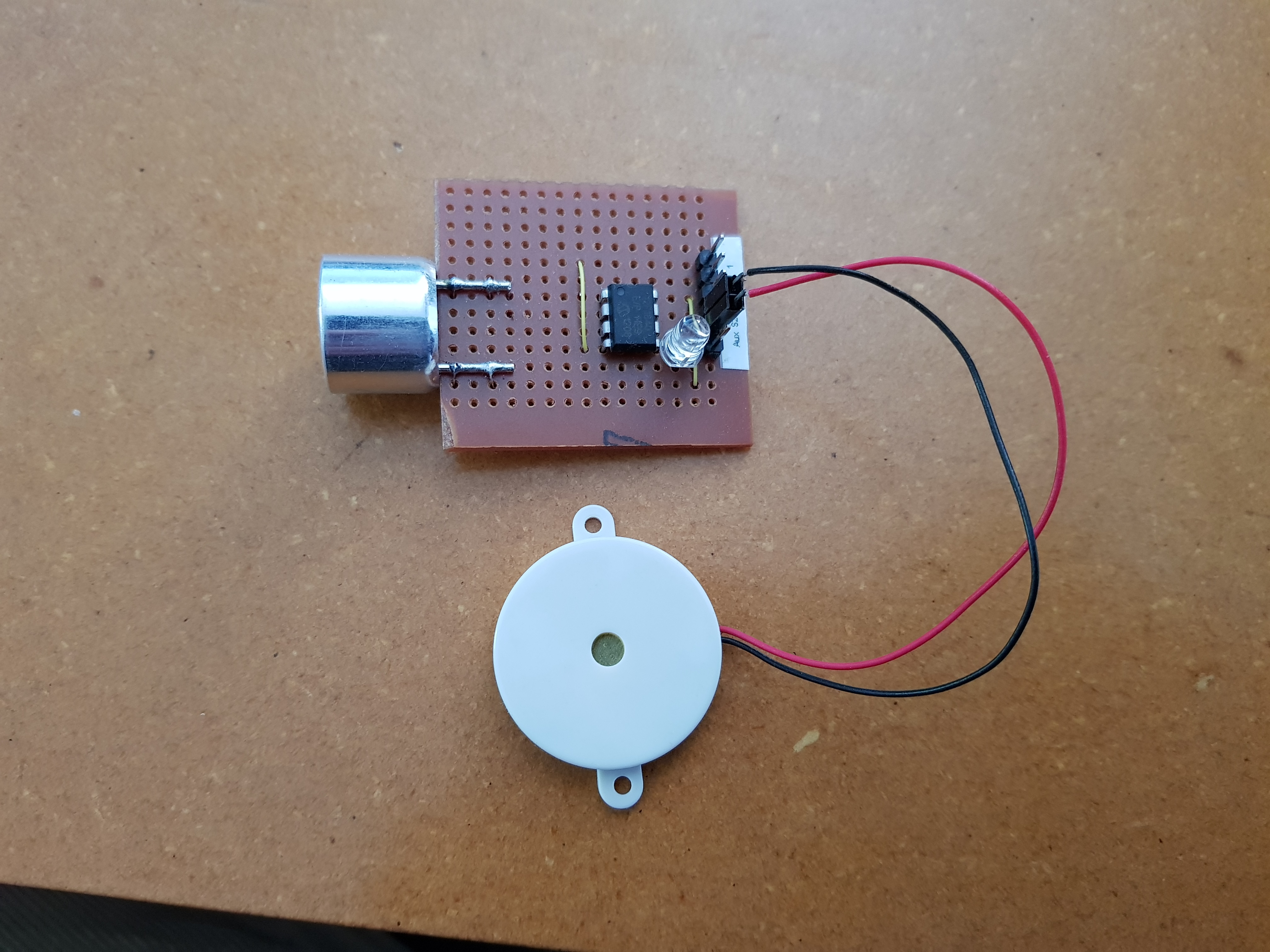
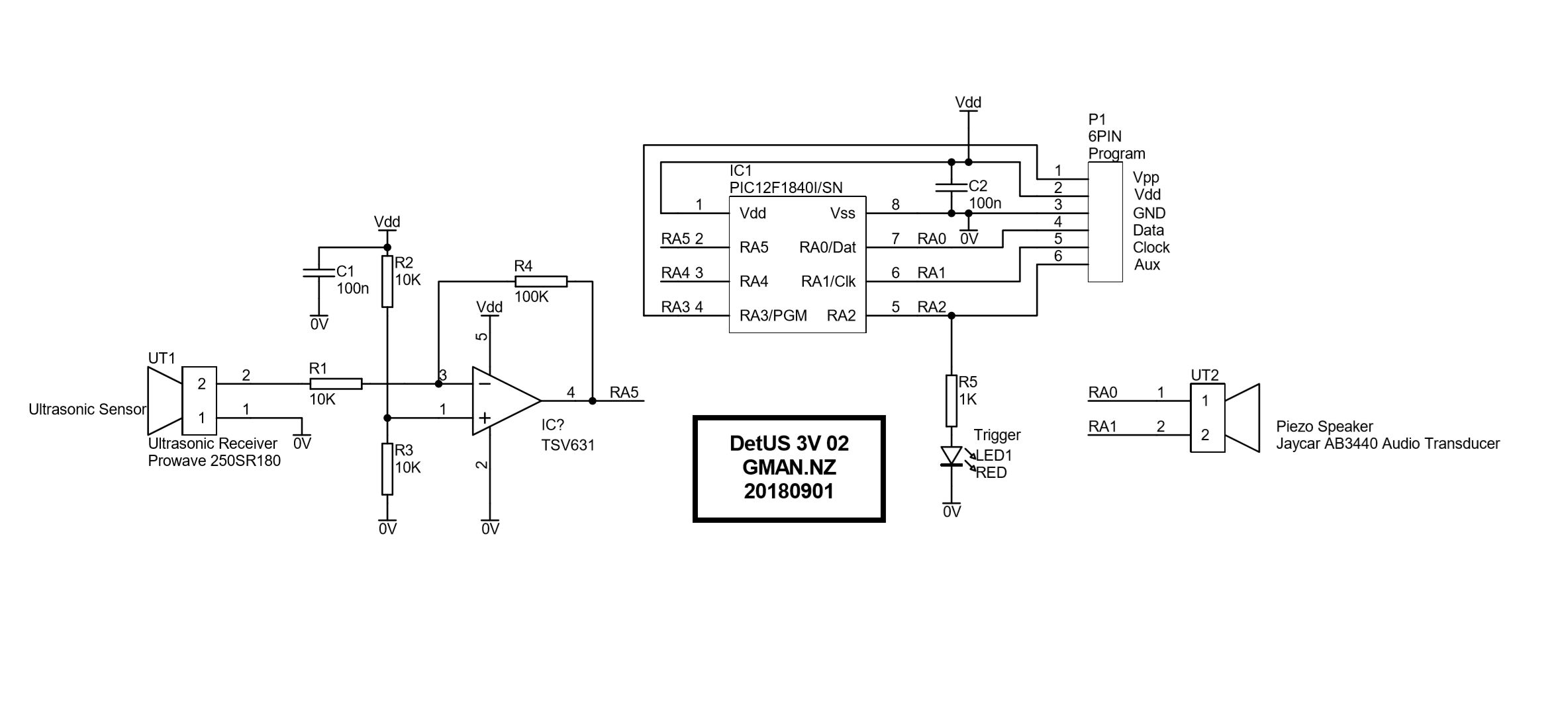
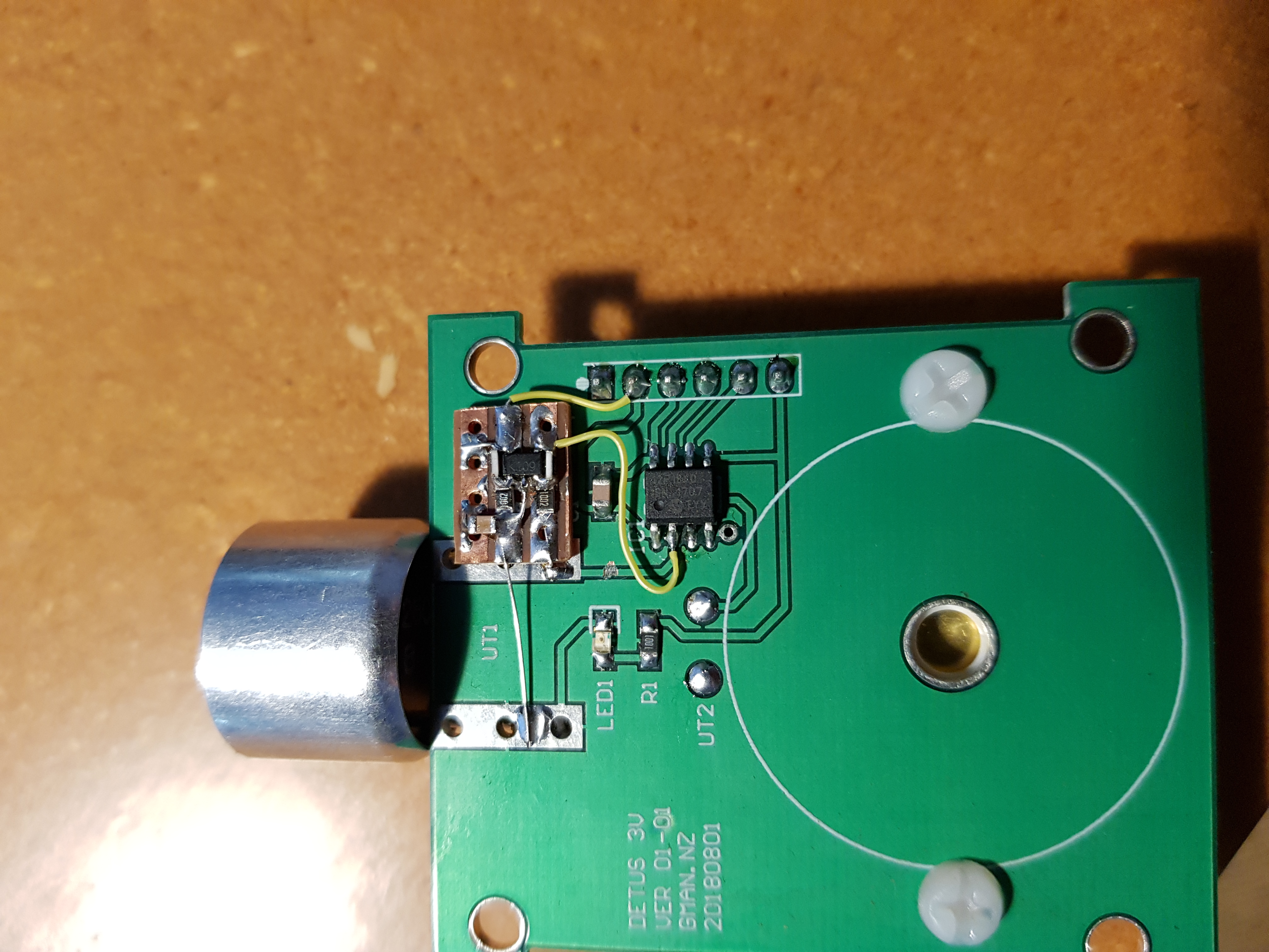
4 September 2018 Put together an Ultrasonic Detector. Based on PicoBat by Bruno Gavand that used a PIC12F683. Essentially the Ultrasonic receiver transducer provides the clock to the microcontroller. As the microcontroller divides the clock by 4, a 25kHz ultrasonic signal becomes 6kHz in the piezo speaker. The microcontroller clock input has a schmidt trigger logic level input and required an amplifier to boost the transducer signal.
Chip Settings #chip 12F1840 #config OSC=ECL, FCMEN=OFF '=================================================== '==== DetUS 01 '==== based on PicoBat by Bruno Gavand that used a PIC12F683 '==== 22 August 2018 '==== gman.nz '==== compiled with GCBasic '=================================================== ' ' I/O ' RA0 Output to Piezo speaker ' RA1 Output to Piezo speaker ' RA2 Output to LED ' RA3 not used ' RA4 not used ' RA5 Clock input from ultrasonic Piezo sensor ' '==== Main routine ' Start: ' set wpua5 = 0 ' dir porta.0 out dir porta.1 out dir porta.2 out ' set porta.0 0 set porta.1 1 set porta.2 0 ' Do Forever lata = lata xor 0b111 loop '==================================================
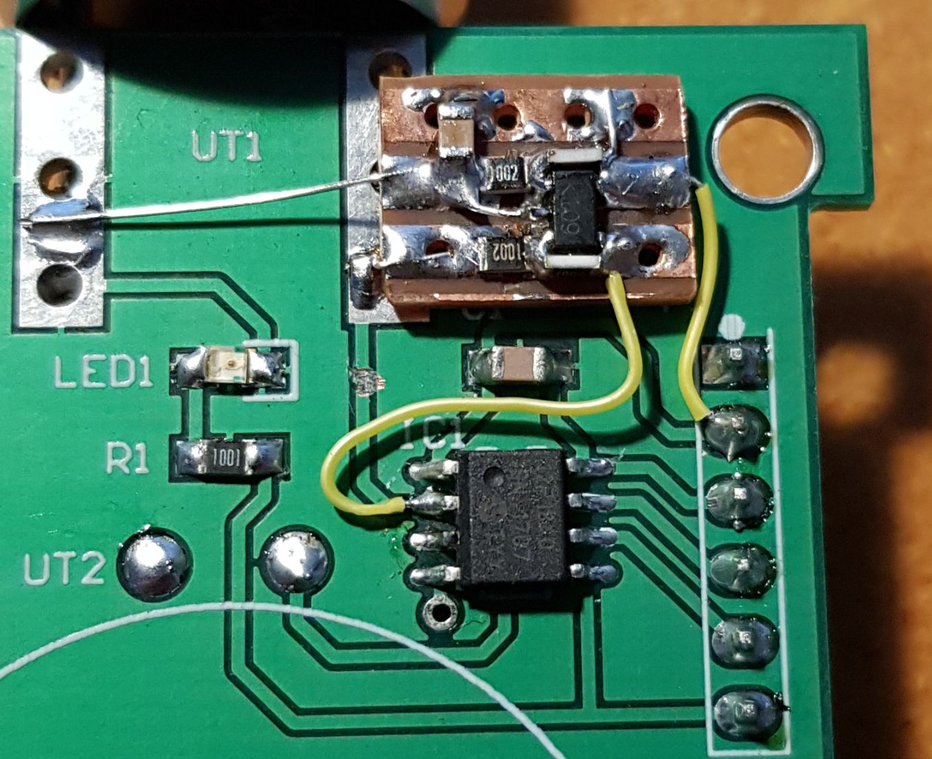
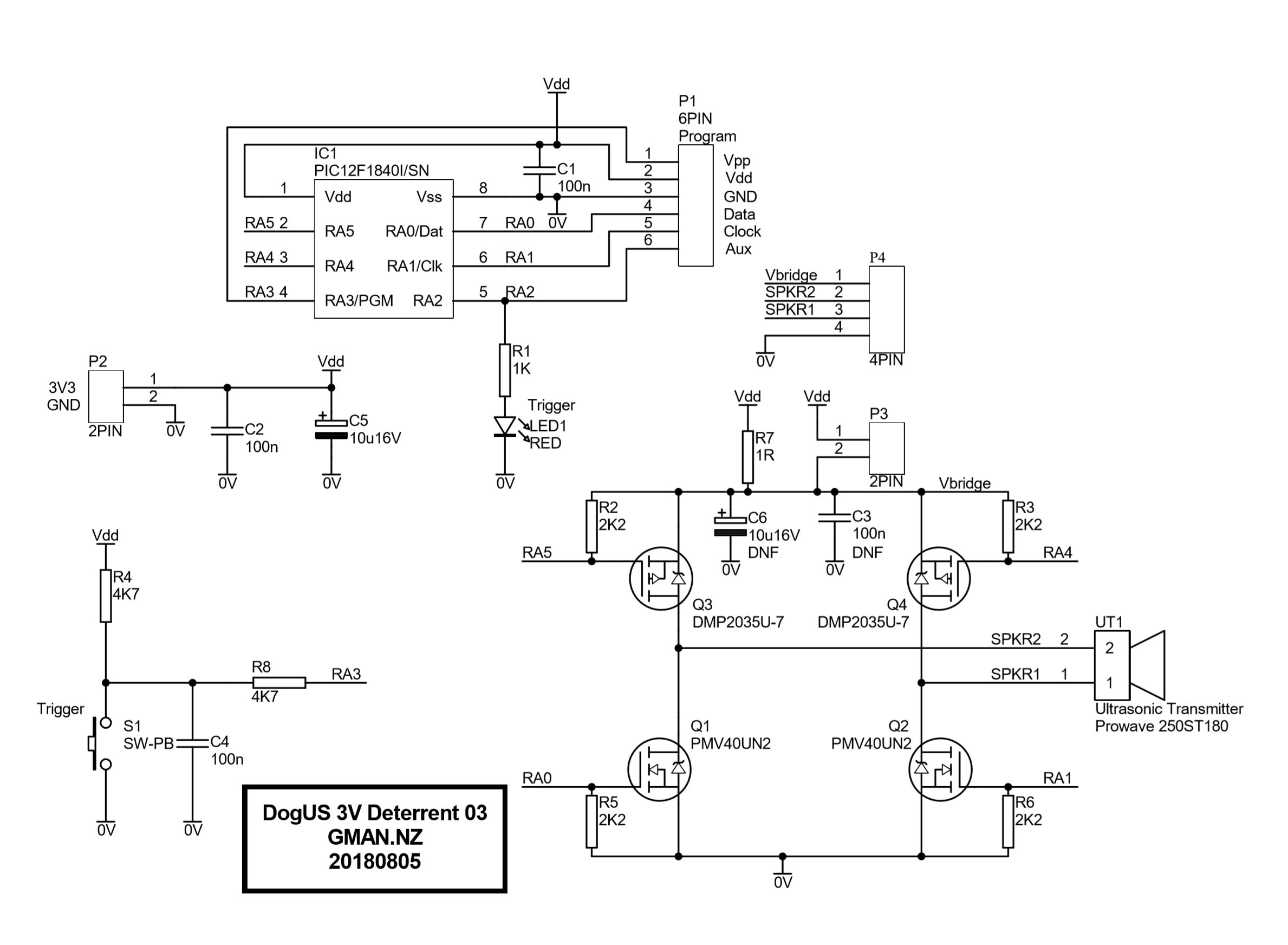
10 August 2018 Decided to build an Ultrasonic Dog Deterrent to try and control a family dog from being a nuisance. The deterrent proved effective and certainly turned the dog away. The simple design needs improvement as it was built quickly with very little test equipment. Timing probably needs tuning to maximise output power... Loops need to be checked for symmetry... Transistor bridge needs to be checked to make sure that break-before-make switching is correct... Microcontroller needs to be put in sleep mode when idle to prolong battery life...
;Chip Settings #chip 12F1840,32 #config OSC=INTOSC, CLKOUTEN=OFF, MCLRE=OFF, WDTE=OFF, BOREN=OFF ' ;Variables Dim acount As word '=================================================== '==== DogUS 03 '==== 18 July 2018 '==== gman.nz '=================================================== ' 'I/O ' RA0 Output to Q1, high drives transistor on. ' RA1 Output to Q2, high drives transistor on. ' RA2 Output to LED Status (hi for LED) ' RA3 Input from Trigger switch. ' RA4 Output to Q4, low drives transistor on. ' RA5 Output to Q3, low drives transistor on. ' '==== Main routine ' Start: ' alloff ' ' check if Test button is low dir porta.3 in ' start1: wait 100 ms if porta.3 = 0 then goto start2 else goto start end if ' start2: ' flash LED on startup dir porta.2 out set porta.2 1 wait 200 ms set porta.2 0 ' start3: ' ' blast 25kHz (40us) for 40us x 50000 = 2 sec for acount = 1 to 50000 q1q4on wait 15 us q2q3on wait 15 us next acount ' ' flash LED dir porta.2 out set porta.2 1 wait 200 ms set porta.2 0 ' if porta.3 = 0 then goto start3 else goto start end if ' '====================================================== ' Function Alloff 'set LATA= 0x30 ' preset outputs: Q1,Q2,Q3,Q4 off ' set porta.0 0 set porta.1 0 set porta.4 1 set porta.5 1 ' ' Q1 N Chan dir porta.0 out ' ' Q2 N Chan dir porta.1 out ' ' Q4 P Chan dir porta.4 out ' ' Q3 P Chan dir porta.5 out ' 'make doubly sure set porta.0 0 set porta.1 0 set porta.4 1 set porta.5 1 End Function
Function Q1Q4on 'make sure Q2,Q3 are off set porta.1 0 set porta.5 1 wait 1 us ' 'now turn on Q1,Q4 set porta.0 1 set porta.4 0 End Function
Function Q2Q3on 'make sure Q1,Q4 are off set porta.0 0 set porta.4 1 wait 1 us ' 'now turn on Q2,Q3 set porta.1 1 set porta.5 0 End Function
|