![]()


![]()
Solar Motion Toys
|
I have a collection of Solar Powered Motion Toys on the window sill behind my computer desk. Two of them have died or only give small kicks when the sunlight falls on them. Basicaly they have a small magnet on a pendulum and a bit of electronics to maintain the swing of the pendulum. My initial thought was that the capacitor across the solar cell had failed... easiest component to change... no improvement!
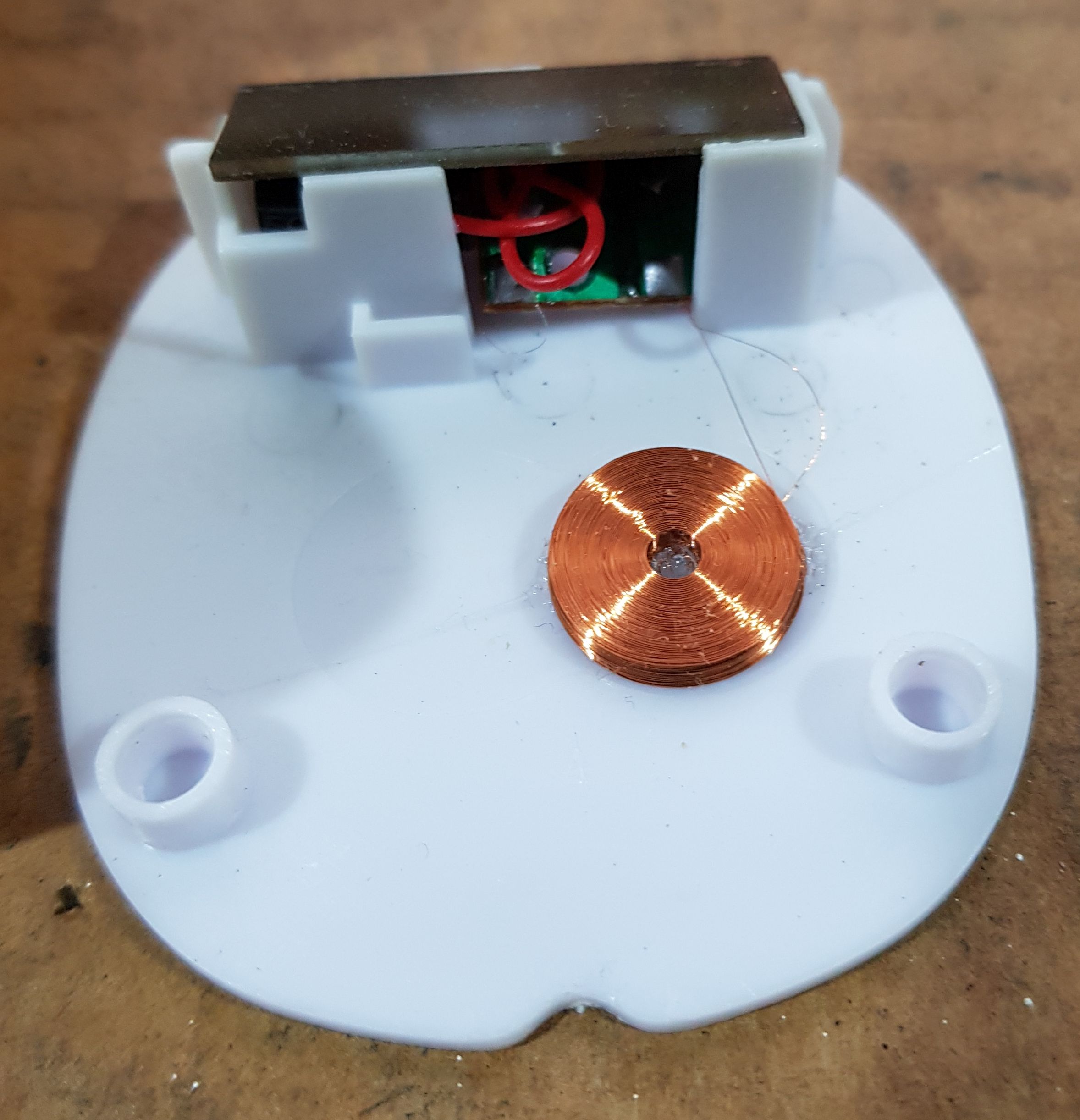
7 September 2019 Whats inside? Solar cell, circuit board and coil:
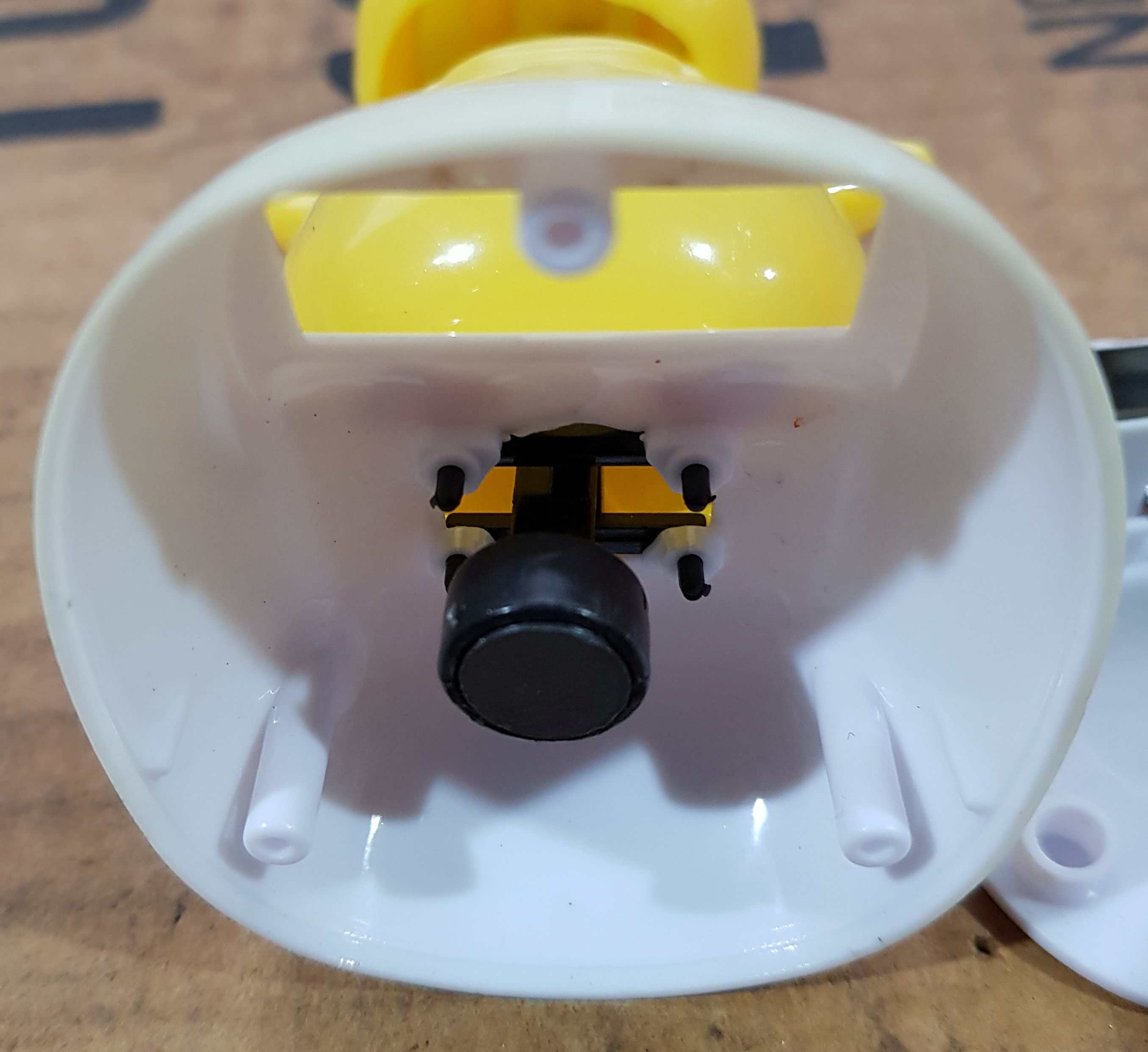
The pendulum and magnet:
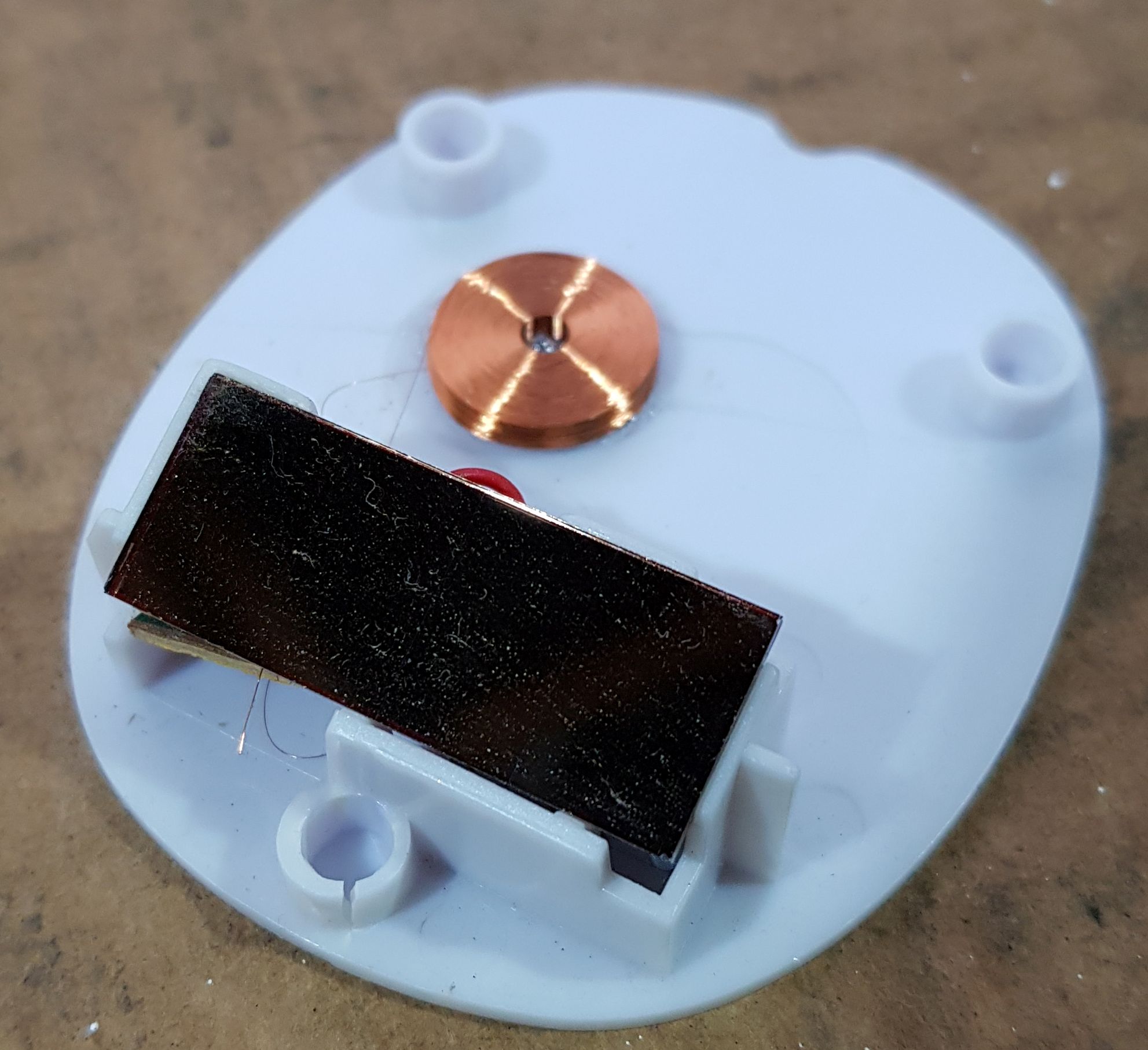
Another view of base:
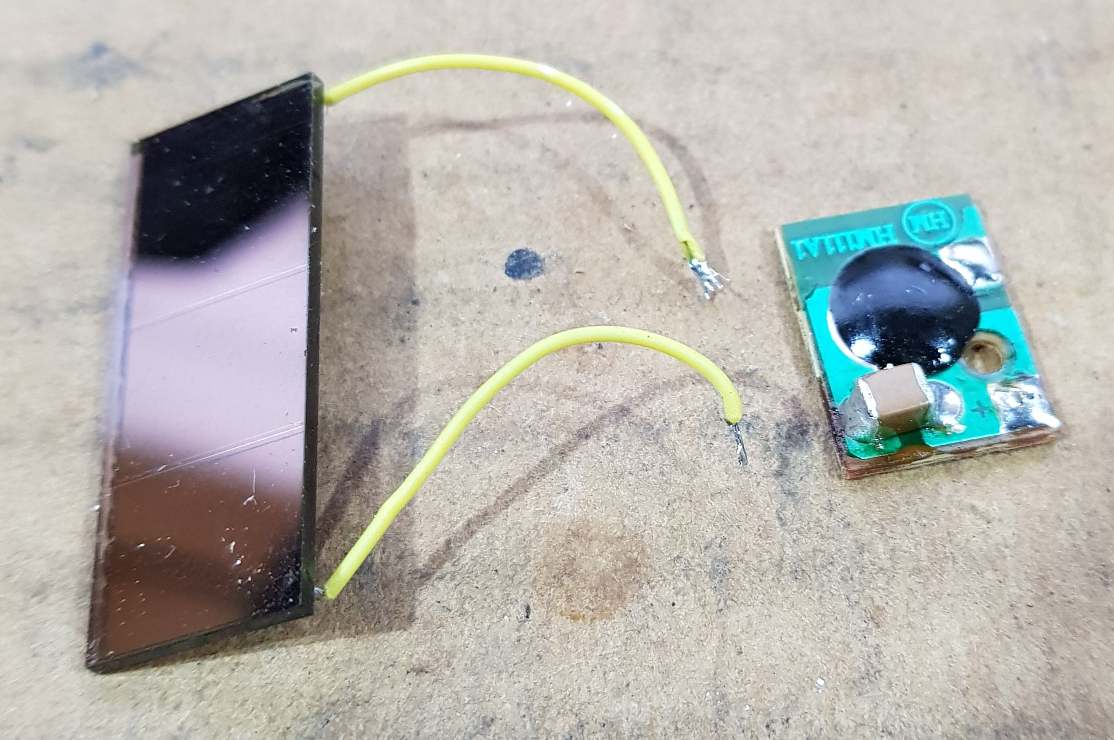
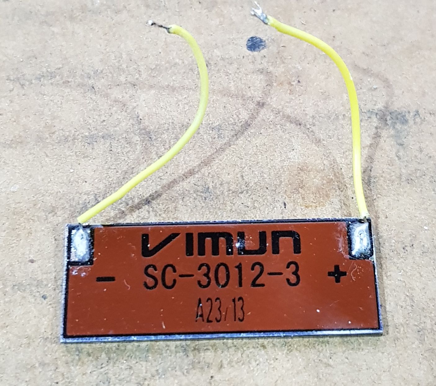
Solar cell and circuit board:
Back of solar cell:
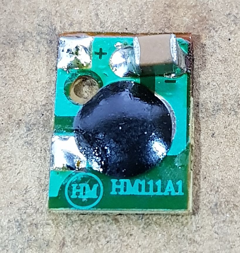
Circuit board:
Another engineer has looked at what makes these toys tick: https://ez.analog.com/university-program/b/blogs/posts/solar-powered-motion-toy-tear-down
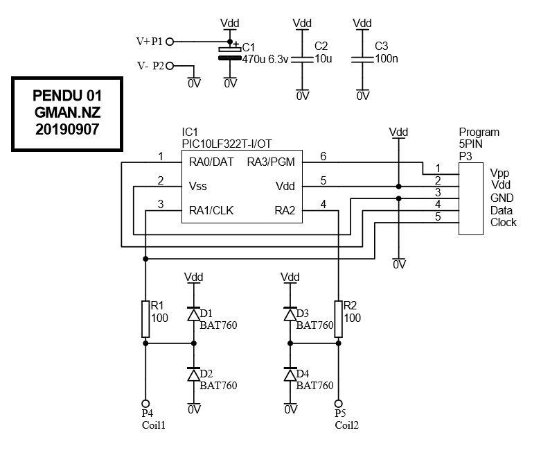
7 September 2019 I decided to try my hand at making new electonics myself. Based on some simple tests on the solar cell and the coil I have decided to use a Microchip PIC10LF322 microcontroller IC which can operate down to 1.8v. It is unknown at present what the level of voltage swing of the coil will be when the toy is fully operational. It was noticed that back emf spikes from the coil were as high as 50v. My circuit has clamping diodes to prevent damage to the microcontroller IC. I have given myself various options to drive the coil: single end and tied to 0v, single ended and tied to Vdd and push-pull where the coil is driven on both half cyles of the swing. Schematic:
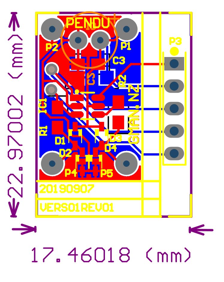
Printed Circuit Layout:
Terminal added to base:
5 September 2019 Made a few measurements of the toy: Solar cell output 1.8 to 2.3v open circuit... medium to strong sun light. 1.7 to 2.3v with 100k load up to 1.8v with 1.5k load Coil resistance 479 ohms Circuit board 15 x 11 mm Solar cell 29 x 11 mm Manually applied 1.5v from a battery directly to coil gives a very good swing of toy.
|