
![]()


![]()
XBee Adapter with MicroChip PIC16F18344, PICkit2 programmer, GCBasic compiler.
I have pretty much stopped work on this project in favour of using Bluetooth LE modules. I did look at ESP8266 WiFi modules but have now decided on Laird BL652 modules. See my Bluetooth LE page.
Want a wireless link from a gate switch with an audible alarm in my house.
- Must do link self check if there is a battery or communication fault
- A platform for learning about XBee modules, PIC16F18344 microcontrollers and programming.
- XBee uses similar communication technology found in ubiquitous cell phones.
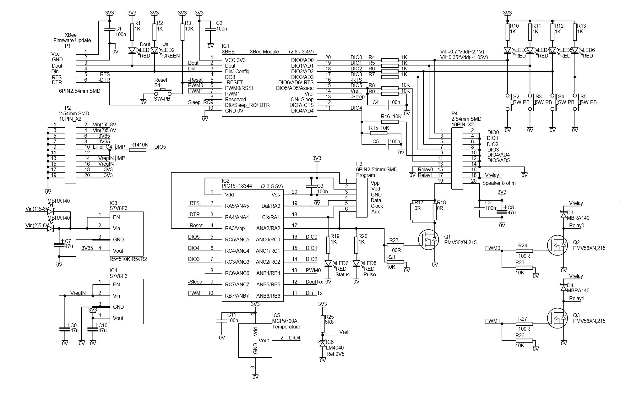
Schem 15 - This is it - for now!:
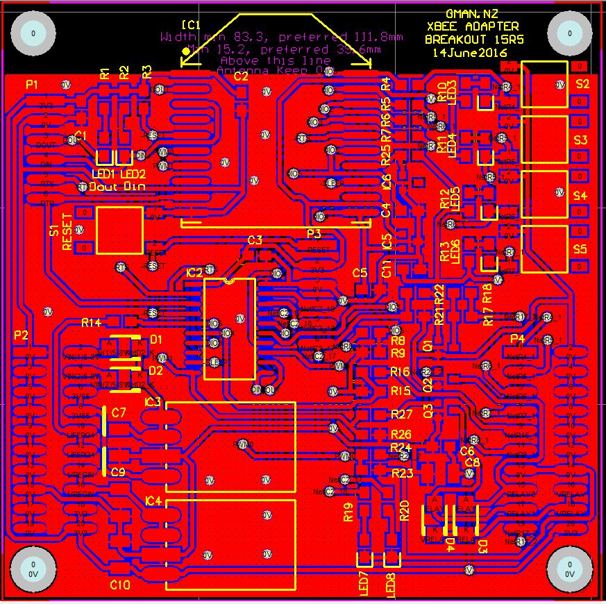
PCB 15r5 (77.7x77.7mm):
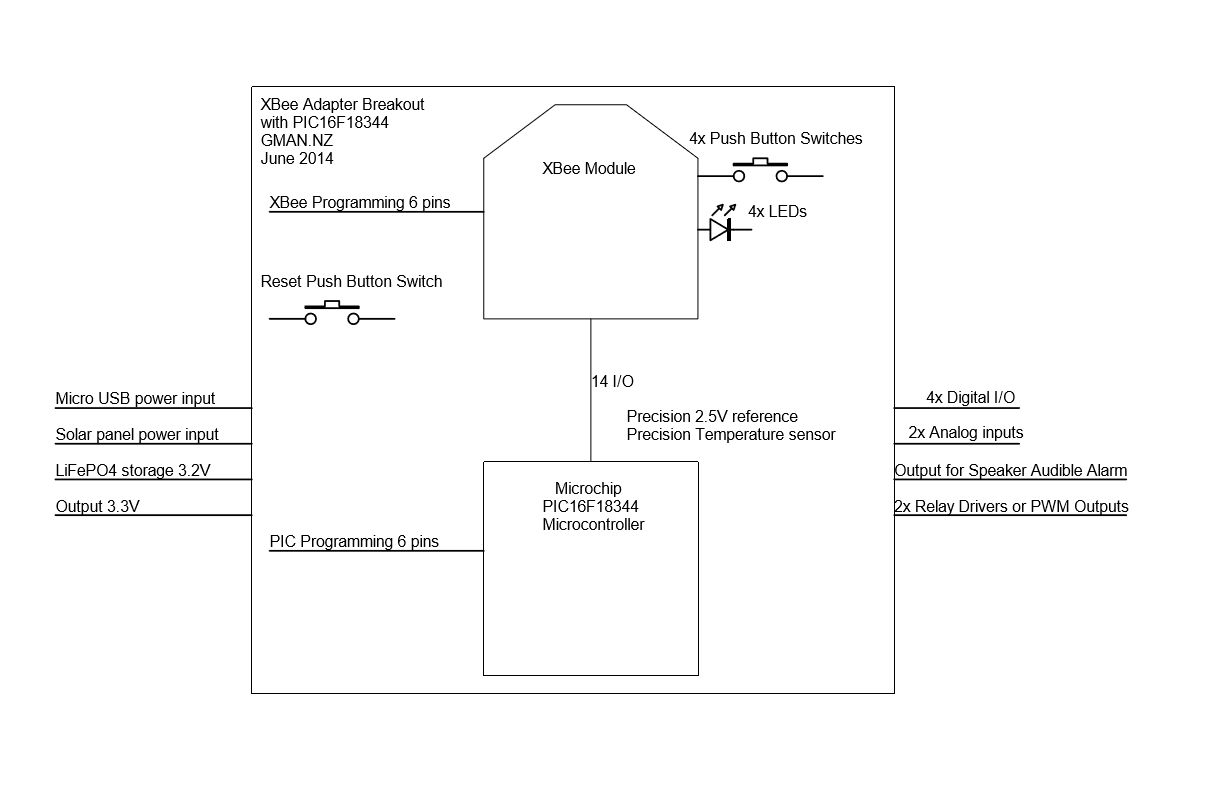
XBee Breakout Block Diagram:
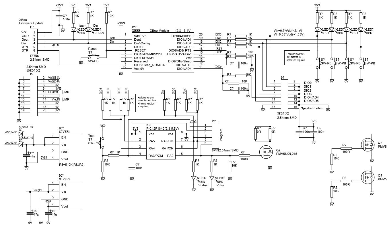
Schem 09 - Getting closer:
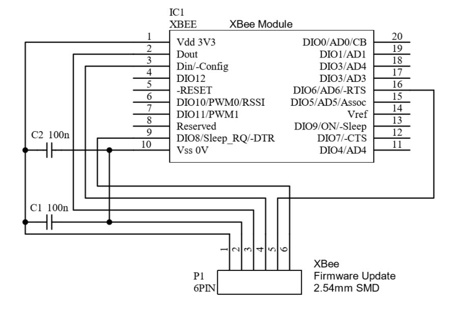
XBee Prog Adapter Schem 01:
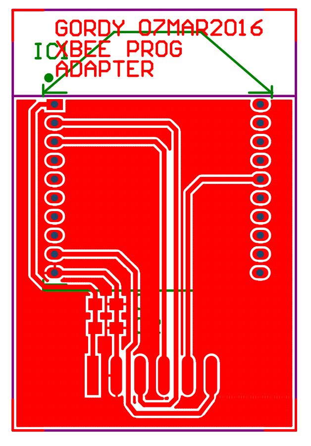
XBee Prog Adapter PCB 01:
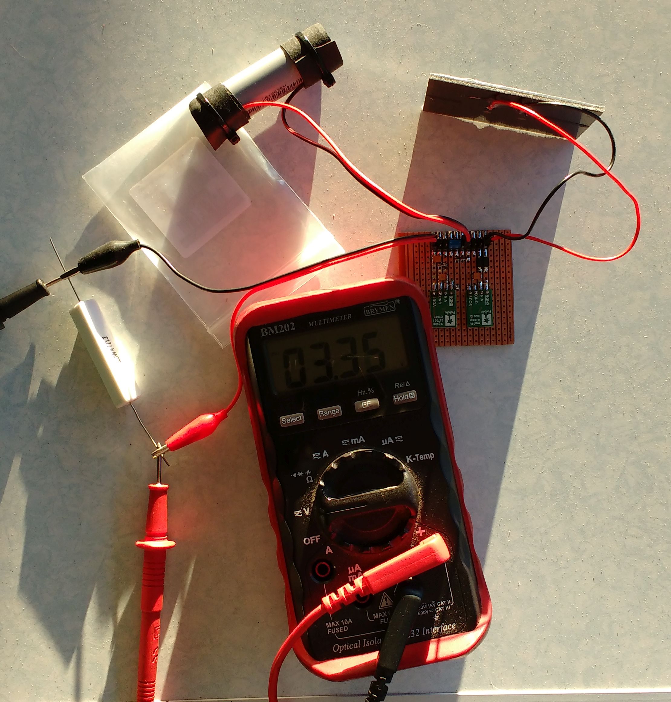
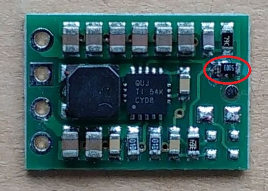
Regulator tests: Solar panel (6v), LiFePO4 cell (3.65v), Output 3.3v, Load 47R (70mA).
Regulator test board
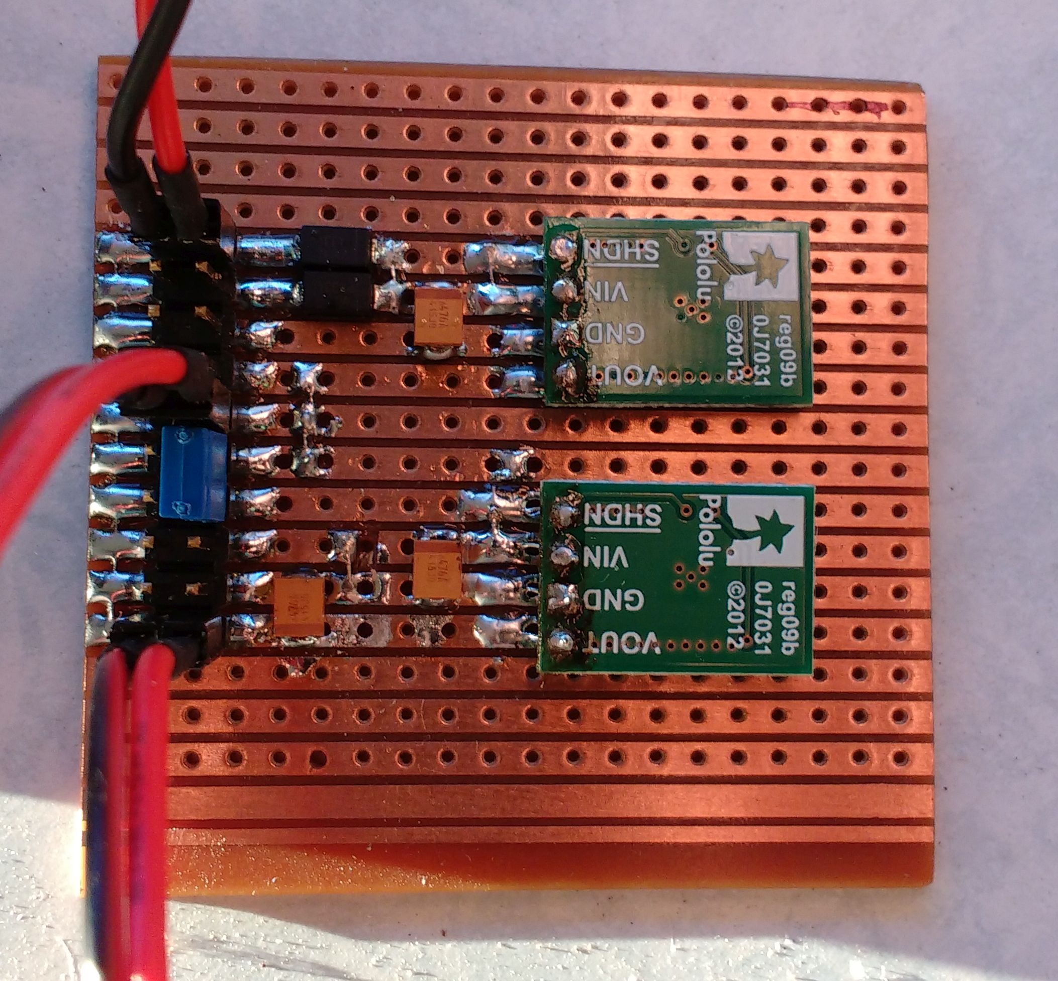
Pololu S7V8F3 with 510k added to change output voltage from 3.3 to 3.65 volts.
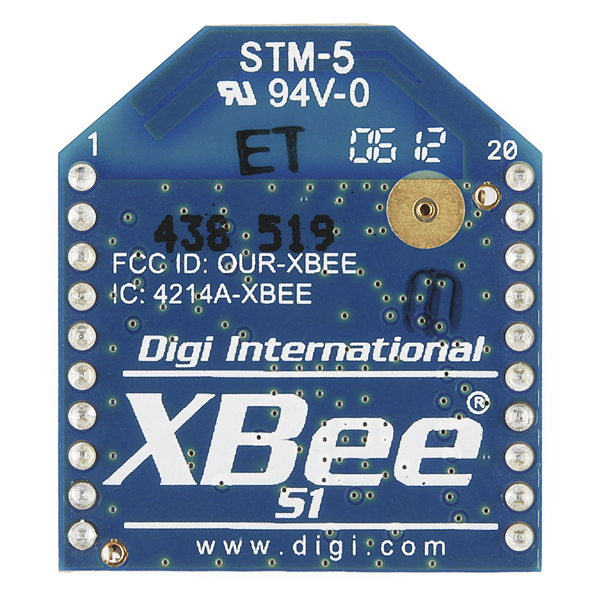
XBee module
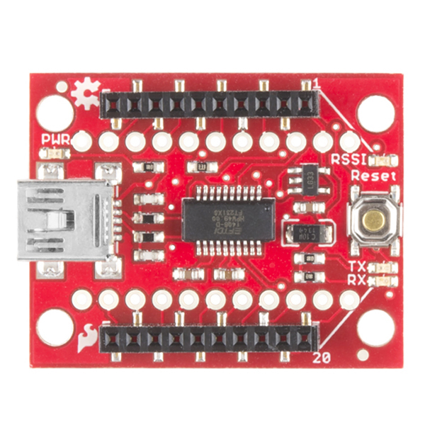
XBee explorer adapter USB
Specification
Use XBee module for communications on 2.4GHz.
Use Microchip PIC16F18344 - was PIC12F1840
Use GCBasic for programming the PIC chip.
In situ programming of PIC chip by 6 pin program header
In situ programming of XBee by 6 pin program header
Run on power sources: USB, Solar, with LiFePO4 cell for storage.
Start of project
29 February 2016
Decided on project concept based on internet searches.
Created a schematic.
Decide on components
4 March 2016
Created this web site.
6 March 2016
Updated to schematic 06. Dropped components onto PCB 06.
Had to create quite a few schematic symbols and foot prints for this project,
7 March 2016
XBee adapter schematic now revision 07. LEDs re-arranged to show direct switch status.
XBee program adapter schematic and PCB designed to plug into standard XBee USB adapter.
Looked at simulation options for LMR16006 using Texas Instruments Tina.
28 May 2016
XBee adapter schematic now revision 09.. Pololu S7V8F3 regulators used for power supply.
Prototype power supply built and load tested.
14 June 2016
XBee adapter schematic now revision 15.. Decided to change the PIC12F1840 to a PIC16F18344 so that interfacing to the XBee module can be changed in software. Double sided PCB designed and manufactured in China by PCBWAY. Chips and other components ordered and I should be able to start assembly soon.